
Users Guide

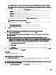


Table Of Contents
- Active System Manager Release 8.3.1 User’s Guide
- Overview
- Getting started with ASM 8.3.1
- Initial Setup
- Dashboard
- Services
- Deploying service
- Add existing service
- Viewing service details
- Editing service information
- Deleting service
- Exporting service details
- Retrying service
- Viewing all settings
- Migrating servers (service mobility)
- Migrating servers
- Upgrading components
- Adding components to an existing service deployment
- Deleting resources from service
- Templates
- Managing templates
- Viewing template details
- Creating template
- Editing template information
- Building template overview
- Building and publishing template
- Importing template
- Exporting template
- Uploading external template
- Editing template
- Viewing template details
- Deleting template
- Cloning template
- Deploying service
- Deploying multiple instances of service
- Adding Attachments
- Decommissioning services provisioned by ASM
- Component types
- Component combinations in templates
- Additional template information
- Managing templates
- Resources
- Resource health status
- Resource operational state
- Port View
- Resource firmware compliance status
- Updating firmware
- Removing resources
- Viewing firmware and software compliance report
- Discovery overview
- Configuring resources or chassis
- Removing discovered resources
- Configuring default firmware repository
- Running firmware compliance
- Configuring global chassis settings
- Configuring unique chassis settings
- Configuring unique server settings
- Configuring unique I/O module settings
- I/O module configuration
- Completing the chassis configuration
- Adding or editing Chassis Management Controller (CMC) user
- Adding or editing Integrated Dell Remote Access Controller (iDRAC) user
- Updating resource inventory
- Viewing resource details
- Understanding server pools
- Settings
- Troubleshooting

The table lists ports that are available in each I/O module in separate columns.
• Clear the Congure the uplinks on each I/O Module Independently check box to congure the same ports as uplink ports
across all I/O modules.
The table displays the following information:
– I/O modules (Model Name) that is present in each fabric.
– Ports that are available in each I/O module.
4. In the table, select the Quadport mode check box if you want to run the port in Quad mode.
When a 40 GbE port is run in quad mode, it provides four 10 GB Ethernet interfaces that number sequentially starting with the
port number of the 40GbE interface. For example, when
Quadport mode is enabled on the GbE port number 33, it makes four
10GbE links with the port numbers 33, 34, 35, and 36.
5. From the drop-down list next to the corresponding port numbers, select the uplink that you want to congure on each port.
NOTE: Uplink is an interconnect (also referred to port-channel, or grouping of ports) which is created on a switch by
creating a connection to other switches in a networking environment. ASM can congure uplinks on MXLs, I/O
Aggregators, FN410S, and FN2210S switches—I/O modules.
6. Click Next to congure uplink port on all chassis independently.
NOTE: Uplink is an external connection from chassis switch to customer network environment. Customer is still
required to congure corresponding ports and uplinks on the top of rack switches, ASM only congures the chassis.
Upload Switch Conguration File
This feature is supported for MXL in M1000e Chassis only.
By using this feature, you can upload a precongured switch conguration le instead of conguring through the I/O Module
Conguration.
To upload switch conguration le:
1. Select Upload Switch Conguration File option. After you select the option, File Name, File Description eld, Upload File eld
tab are appeared.
Enter the result of your step here (optional).
2. Type the le name which you want to upload in File name eld.
3. Type a le description which about the le in File Description eld.
4. Click Browse beside Upload File tab. It directs you to your local system where you have saved the le.
5. Select the le and click Open to upload it.
NOTE: After you upload the switch conguration le, it gets uploaded on switch. It takes existing IPs from the
switch and pulls it out and upload to the conguration le. It gets applied on all selected switches what you have
chosen to congure. It also pulls out the host name and credentials.
Dening uplinks
1. On the Uplink Port Conguration page of the Congure Chassis wizard, in the Congure Uplinks area, click Dene Uplinks.
2. In the Dene Uplinks dialog box, click Add Uplink, and enter the following:
a. Enter the name for the uplink.
b. From the Port Channel drop-down list, select the port channel that you want to create on the switch.
c. From the Network Type drop-down list, select one or more networks that you want to assign to the uplink.
The Network Name(s) column displays the networks that are assigned to the uplinks.
To delete an uplink, click the Delete icon left to the corresponding uplinks.
3. Repeat step 2 to dene multiple uplinks.
4. Click Save.
After you dene and save uplink, uplink is available to get applied to switch.
80