
Installation Guide

90°
90°
A
B
s
s
B
A
A
B
s
s
B
A
A
6
(152)
BC
9-1/16
(230)
3/4
(19)
(25)
1
1-1/16
(27)
1-3/4
(44)
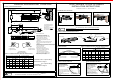
Right h
an
d do
or illustrated
same d
im
ens
ions apply to
left han
d
door
.
Measu
red
fro
m hinge Cent
er
.
Dimens
io
ns a
re in
inches
(mm)
Do not
sc
ale
drawing
6
3-1/2
Dimens
io
n
Model
No
.:
DO-01
Dimen
sio
n"A
"
Openin
g
Ang
le
Inch
mm
152
89
120°
180°
Speed
Re
gul
ating
Valves
D
oor
frame
Door
Shoe
Arm Sc
re
w
P
inion C
ap
Positio
n o
f ar
ms and index
se
ttin
gs
Door F
ram
e
Right H
an
d(R
H)Door,or Le
ft H
and
Reverse(LH
R
)doo
r
Pinion
fla
t
Positio
n t
he m
ian arm to th
is
orienta
tio
n fo
r preloading.
INSTA
LL
ATI
ON STEPS:
1.Selec
t o
pen
ing angle of t
he
doo
r.Use
Dime
ns
ions
as shown to
dr
ill m
ounting holes
o
n
door
an
d do
or frame.
2.Attac
h t
he c
loser body to
do
or
with speed
regul
ati
ng v
alves toward
th
e hin
ge.
3.Asse
mb
le m
ain arm to cl
os
er to
p pinion shaf
t.
4.Attac
h t
he f
oerarm shoe
to
the
door frame.
5.Adjus
t l
engt
h of the forea
rm
to p
osition forea
m
at
right a
ng
le t
o the door lea
f w
hen
connected t
o
main
arm
at
elbow. Use w
as
her
and screw
provid
ed
to
secure pivot c
on
nec
tion.Tighten
lockn
ut o
n fo
rearm.
6.Snap
pi
nion
cap over spi
nd
le a
t bottom of clo
se
r.
7.Adjus
t c
lose
r.
INSTA
LL
ATIO
N STEPS:
1.Selec
t o
pen
ing angle of
the
doo
r.Use dimen
sio
ns a
s
show
n t
o dr
ill mounting h
ole
s o
n door and fr
am
e.
2.Attac
h t
he c
loser body to
do
or f
rame with sp
ee
d
regul
ati
ng
valves towar
d th
e h
inges.
3.Asse
mb
le m
ain arm to th
e c
los
er bottom pin
ion
sha
ft.
4.Attac
h t
he s
hoe and fore
arm
to
the door.
5.Adjus
t l
eng
th of the forea
rm
to
position fore
am
at r
ight
angle
to
the
frame when
co
nne
cted to main
arm
at
elbow
. U
se
washer and s
cr
ew p
rovided to se
cu
re
pivot
co
nne
ction.Tighten
lo
cknu
t on forearm.
6.Snap
pi
nion
cap over sp
ind
le a
t bottom of th
e c
lose
r.
7.Adjus
t c
lose
r. (Same to P
ag
e 2
)
Pinion
fla
t
Door
Door F
ram
e
Positio
n o
f ar
ms and index
se
ttin
gs
180°
120°
89
152
mm
Inch
Openin
g
Ang
le
Dimens
io
n"A"
DO-01
Model
No
.:
Dimen
sio
n
3-1/2
6
Right h
an
d do
or illustrated
same d
im
ens
ions apply to
left han
d
door
.
Measu
red
fro
m hinge Cen
ter
.
Dimen
sio
ns a
re in
inches
(mm)
Do not
sc
ale
drawing
Stop fa
ce
Speed
re
gula
ting
valves
Hinges
Center
line
6
(152)
A
1-3/4
(44)
3/4
(19)
1/2
(13)
(39)
1-1/2
9-1/16
(230)
Door
Leaf
Pinion
Ca
p
Screw
an
d
washer
shoe
Door
Frame
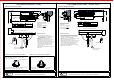
INSTALLTION INSTRUCTIONS
TOP JAMB MOUNTING
(
PUSH SIDE
)
3
2
!
Caution
!
Caution
REGULAR ARM(PULL SIDE)
IMPRO
PE
R INSTALLA
TI
ON OR ADJU
S
TMENT MAY
R
ESULT IN PE
R
S
ONAL INJUR
Y
OR PR
O
P
ERTY DAMA
G
E. FOLLOW
A
L
L INSTRUCT
I
O
NS CAREFU
L
L
Y.
INSTA
L
LATION INSTRUCTIONS
Turn B
C re
gula
ting valve clo
ckw
ise fo
r a harder cu
shio
n an
d
counte
r-clo
ckwi
se for a softe
r cu
shion
.NEVER clos
e th
is va
lve completel
y.
BC
This va
vle
con
trols
latching
s
pee
d
Turn sp
ee
d re
gulating valv
e c
oloc
kwise to slow
d
own
or counter
clockw
ise
to s
peed up doo
r m
ove
ment.
2
1
This va
vle
co
ntrols
sweep
sp
eed
Adjust
the
spr
ing power as
ch
art
in page 1. DO
N
OT
exceed
the ma
xim
um
turns.The sp
rin
g po
wer has bee
n r
eset
on size 2
in facto
ry.
Tur
n this screw c
loc
kwi
se to increas
e o
r co
unter
clockw
ise
to d
ecrease pow
er
.
Power
ad
justm
ent Nut.
POWE
R
S
IZE AND BA
CK
CHECK AD
J
U
STMENT
SWEEP
A
ND LATCHIN
G
SPEED ADJ
U
S
TMENT
Hinges
C
ente
rline
Positio
n o
f the
main arm
prior to
pr
eloa
ding
Top jam
b
IMPRO
PE
R INSTALLA
TI
ON OR ADJU
ST
MENT MAY
RE
SULT IN PE
R
S
ONAL INJUR
Y
OR PR
O
PERTY DAMA
G
E. FOLLOW
A
L
L INSTRUCT
I
O
NS CAREFU
L
L
Y.
BC
Valve
BC
Valve