
Installation Instructions
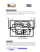
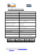
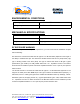
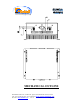
Table Of Contents
- AND
- BOOSTER
- The switch on the RF amplifier enables the AGC function. If the AGC is disabled then the amplifier gives maximum gain.
- The AGC ON/OFF and GAIN SETTING functions for the up link path are reached by opening the small slide door located on the Booster left side, adjacent to the BASE antenna port. For the down link path the door is on the right side adjacent to the MOBILE an
- Limited Warranty

Dekolink Wireless Ltd., 16 Bazel St., Qiryat-Arieh Petah-Tikva Israel, 49510
Tel: 972-3-9180-180; Fax: 972-3-9180190 Email: marketing@dekolink.com
:ELECTRICAL SPECIFICATIONS
Frequency Range (MHz) See table
Passband Gain @Min attenuation 40 dB nominal
Passband Ripple +/- 1.5 dB typical
Manual Attenuation Range 0 to 30 dB in 2 dB step
Isolation between up and down link 70 dB min
Noise Figure 6.0 dB max
3rd Order output Intercept point
Downlink +50 dBm typical
Uplink +43 dBm typical
3rd Order IMD
Downlink @2 tone +27 dBm each
Uplink @2 tone +20 dBm each
45 dBc typical
45 dBc typical
AGC Factory Power Preset Downlink +30 dBm nom.
Uplink +24 dBm nom.
Impedance level 50 ohms
V.S.W.R In/Out 1.5 : 1 max
AGC Attenuation Range 25 dB typical
AGC Selection By ON/OFF Switch
AGC LED Indication LED turn ON when power reaches AGC Set
Power Level. (both at On and Off Positions).
Power Supply : 110/220V AC, 50-60 Hz
System Frequency Range
SYSTEM TYPE
MODEL No
DOWN-
LINK
UP-
LINK
E-SMR (iDEN) MW-IBDB-ESMR-10W40A 851-866 806-821
SMR - 900 MHz MW-IBDB-SMR-10W40A-PS9 935-941 896-902
;
Web site: www.dekolink.com Rev 0 02/03 Page 6 of 9