
Installation Instructions
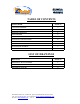
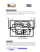
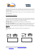
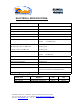
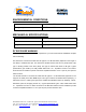
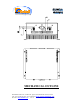
Table Of Contents
- AND
- BOOSTER
- The switch on the RF amplifier enables the AGC function. If the AGC is disabled then the amplifier gives maximum gain.
- The AGC ON/OFF and GAIN SETTING functions for the up link path are reached by opening the small slide door located on the Booster left side, adjacent to the BASE antenna port. For the down link path the door is on the right side adjacent to the MOBILE an
- Limited Warranty

Dekolink Wireless Ltd., 16 Bazel St., Qiryat-Arieh Petah-Tikva Israel, 49510
Tel: 972-3-9180-180; Fax: 972-3-9180190 Email: marketing@dekolink.com
TABLE OF CONTENTS
PARAGRAPH PAGE No
BOOSTER OVERVIEW 3
BLOCK DIAGRAM DESCRIPTION 3
BOOSTER OPERATION 4
AGC FUNCTION
4
AGC AND GAIN CONTROLS 5
ELECTRICAL SPECIFICATIONS 6
ENVIRONMENTAL CONDITIONS 7
MECHANICAL SPECIFICATIONS 7
RF EXPOSURE WARNING 7
DEKOLINK WIRELESS LIMITED WARRANTY 9
LIST OF DRAWINGS
DRAWING PAGE No
BOOSTER RF BLOCK DIAGRAM 4
AGC AMPLIFIER 5
MECHANICAL OUTLINE 8
;
Web site: www.dekolink.com Rev 0 02/03 Page 2 of 9