INSTALLATION AND OPERATING INSTRUCTIONS FOR MW-IBDB 10W40 BOOSTER Dekolink Wireless Ltd., 16 Bazel St., Qiryat-Arieh Petah-Tikva Israel, 49510 Tel: 972-3-9180-180; Fax: 972-3-9180190 Email: marketing@dekolink.com; Web site: www.dekolink.
TABLE OF CONTENTS PARAGRAPH PAGE No BOOSTER OVERVIEW 3 BLOCK DIAGRAM DESCRIPTION 3 BOOSTER OPERATION 4 AGC FUNCTION 4 AGC AND GAIN CONTROLS 5 ELECTRICAL SPECIFICATIONS 6 ENVIRONMENTAL CONDITIONS 7 MECHANICAL SPECIFICATIONS 7 RF EXPOSURE WARNING 7 DEKOLINK WIRELESS LIMITED WARRANTY 9 LIST OF DRAWINGS DRAWING PAGE No BOOSTER RF BLOCK DIAGRAM 4 AGC AMPLIFIER 5 MECHANICAL OUTLINE 8 Dekolink Wireless Ltd., 16 Bazel St.
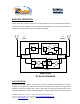
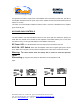
BOOSTER OVERVIEW: The Booster provides an exceptional performances to extend the coverage area of radio communications in buildings and RF shielded environments. The unit is based on a duplexed path configuration, having sharp out of band attenuation for improved isolation between the receiving and transmitting paths. BLOCK DIAGRAM DESCRIPTION: The Downlink path receives the RF signals from base station, amplifies them and transmits them for further distribution to the subscriber.
BOOSTER OPERATION The RF connection is made via two type “N” female connectors. The RF connector labeled “Base” is connected to the base station. The RF connection labeled “Mobile” is connected to the antenna of area to be covered by the Booster; such as inside the building.
the signal level so that the output power of the amplifier does not exceed the preset limit. The LED on the amplifier illuminates when the power output of the amplifier is within the set limit (either when the AGC is On or OFF). The switch on the RF amplifier enables the AGC function. If the AGC is disabled then the amplifier gives maximum gain.
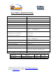
ELECTRICAL SPECIFICATIONS: Frequency Range (MHz) See table Passband Gain @Min attenuation 40 dB nominal Passband Ripple +/- 1.5 dB typical Manual Attenuation Range 0 to 30 dB in 2 dB step Isolation between up and down link 70 dB min Noise Figure 6.0 dB max 3rd Order output Intercept point Downlink +50 dBm typical Uplink +43 dBm typical 3rd Order IMD Downlink @2 tone +27 dBm each 45 dBc typical Uplink @2 tone +20 dBm each 45 dBc typical AGC Factory Power Preset Downlink +30 dBm nom.
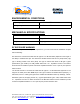
ENVIRONMENTAL CONDITIONS: Operating temperature : - 10°C to + 50°C Storage temperature : - 50°C to + 90°C MECHANICAL SPECIFICATIONS: Size mm(Inch) 265(10.4) x 250(9.8) x140(5.5) RF Connectors N-type Female Weight 8 kg. Approx RF EXPOSURE WARNING In order to satisfy the FCC RF exposure requirements, you must ensure that the installation complies with the following: One antenna is connected via cable that has typical 1~10 dB attenuation (depends on the length of the cable) to the BDA base port.
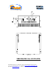
MECHANICAL OUTLINE Dekolink Wireless Ltd., 16 Bazel St., Qiryat-Arieh Petah-Tikva Israel, 49510 Tel: 972-3-9180-180; Fax: 972-3-9180190 Email: marketing@dekolink.com; Web site: www.dekolink.
DEKOLINK WIRELESS LIMITED WARRANTY Dekolink Wireless [Ltd.] (“Dekolink”), manufacturer of this product (the “Product”) warrants to the original purchaser (“Purchaser”) that the Product is free from defects in materials and workmanship for a term that ends on the earlier of twelve (12) months from the date of activation of the Product or fifteen (15) months from the date of shipment of the Product by Dekolink.