
User's Manual
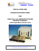
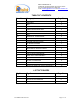
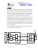
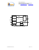
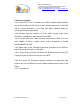
Table Of Contents
- FOR
- IDEN Fiber-optic REPEATER SYSTEM
- 50W WITH DIVERSITY
- & FiberopticBase Interface Unit
- _
- The FBDA is installed near the area to be covered and is connected to the mobile antenna. A Fiberoptic transceiver converts the Downlink optical signals to RF signals and the uplink RF signals to optical signals. A duplexer in the FBDA separates the upli
- of the same antenna for receiving and transmitting. The duplexer has sharp out of band attenuation for better isolation between the receiving and
- transmitting paths and for reduction of out of band interfering signals. A high power amplifier in the downlink path produces high RF power to the antenna. A pre-amplifier is used to drive the uplink signals from the antenna to the Fiberoptic transceiver
- or diversity applications the uplink path is duplicated using separate antenna, filter, pre-amplifier and Fiberoptic transmitter.
- Please refer to installation and operation instructions for FBDA-SMR8-50W-DIV
- Limited Warranty

Dekolink WIRELESS Ltd.
16 Bazel St. Qiryat-Arieh Petah-Tikva, Israel, 49510
Tel- 972-3-9180-180 Fax-972-3- 190-9180
e-mail: marketing@dekolink.com
web www.dekolink.com
1.2 FBDA
The FBDA is installed near the area to be covered and is connected to the
mobile antenna. A Fiberoptic transceiver converts the Downlink optical
signals to RF signals and the uplink RF signals to optical signals. A duplexer
in the FBDA separates the uplink and downlink signals thus enabling the use
of the same antenna for receiving and transmitting. The duplexer has sharp
out of band attenuation for better isolation between the receiving and
transmitting paths and for reduction of out of band interfering signals. A high
power amplifier in the downlink path produces high RF power to the antenna.
A pre-amplifier is used to drive the uplink signals from the antenna to the
Fiberoptic transceiver input to maintain reasonable NF (noise figure) in the
uplink path. The FBDA contains a monitoring unit to monitor the operation of
the active elements inside the FBDA. Whenever a fault occurs an ALARM
signal is sent to the FBIU.
or diversity applications the uplink path is duplicated using separate antenna,
filter, pre-amplifier and Fiberoptic transmitter.
FBDA SYSTEM BLOCK DIAGRAM
Mobile ANT.
BTS
High
pwr
ATTN.
30 dB
Tx
Rx
F/O+
WDM
RF IN
RF Out
optical in/out
optical in
F/O+
WDM
optical in/out
optical Out
FBDA
RF
section
FBIU
FIBEROPTIC CABLE
RUN UP TO 20Km
ATTN.
30 dB
(MAX. 0dBm)
F/O
F/O
RF Out
ATTN.
30 dB
Rx1
ATTN
FO-SMR8-50W SYS1.doc Page 4 of 12