
User's Manual
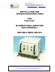
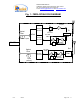
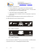
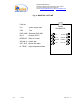
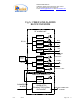
Table Of Contents
- FiberLink(
- BI-DIRECTIONAL AMPLIFIER
- WITH DIVERSITY
- MW-FBDA-SMR8-50W-DIV
- _
- The duplexer serves to frequency separate uplink signals from downlink signals. The duplexer has sharp out of band attenuation for better isolation between the receiving and transmitting paths and for better rejection of interfering signal in the air. In
- The uplink pre-amplifier is a low noise, 45dB gain unit. The amplifier contains AGC control circuitry. When a high power signal is received the automatic level control detects it and reduces the gain so that the output power of the amplifier is constant.
- The LED on the amplifier illuminates when the power output of the amplifier exceeds the AGC power set limit (when the AGC is either ON or OFF).
- The Switch on the RF amplifier enables the AGC function. If the AGC is disabled then the amplifier gives maximum gain for any input.
- The AGC level is factory set to 0 dBm and AGC is set to ON, to prevent high power damage at the Rfiber+ input.
- The FBDA monitor performs the following functions:
- a) Monitors the DC supply voltage of the FBDA. The fault LED illuminates when the voltage is beyond the specified limits.
- b) Monitors the current to each active element and the internal fan. If the current is below or above the specified limits then a LED illuminates.
- c) Monitor the optical receive signal using alarm output of the optical transceiver.
- d) Monitors the Thermostat for high temperature alarm.
- e\) Provides automatic alarm function. Whenever
- e) Provides self test for the alarm functions. The pushbutton switch on the Monitor unit turns on all the alarm LEDs and initiates the summarized alarm.
- 2.7 POWER DISTRIBUTION UNIT
- The power distribution unit acts as DC connection panel. It receives power from the power supply and distributes it to the FBDA units.
- It contains the following functions:
- Fuse and for the DC power coming from the AC power supply.
- Current sampler for the high power 50 Watt amplifier.
- distribution strip for various units.
- 2.8 POWER SUPPLY
- This is a high efficiency switching power supply providing +28 VDC for the 50W amplifier, and a +13.5 VDC for other units.
- In order to satisfy the FCC RF exposure requirements, you must ensure that the installation complies with the following:
- The antenna is connected via cable that has typical 1~10 dB attenuation (depends on the length of the cable) to the FBDA MOBILE port.
- There are two applications: Outdoor and Indoor.
- In the case of Outdoor the type of antenna is omnidirectional (isotropic) with 0 to 2 dBi typical gain, or wide beam with up to 3 dBi gain, and is installed on a mast to cover shadowed, outdoor, area. This antenna must be installed to provide a minimum
- In the case of Indoor coverage the power is split to several, omnidirectional (isotropic) antenna with 0 to 2 dBi typical gain, and distributes to different indoor areas (in building floors, tunnels, basements, parking lots, shopping centers etc.). T
- Less separation is needed if the power is divided into more than 5 antenna covering many floors or areas.
- Fig. 7:MECHANICAL LAYOUT
- Limited Warranty

Dekolink WIRELESS Ltd.
16 Bazel St. Qiryat-Arieh Petah-Tikva, Israel, 49510
Tel- 972-3-9180-180 Fax-972-3- 190-9180
e-mail: marketing@dekolink.com
web www.dekolink.com
1. OVERVIEW:
The FBDA is an interface unit between optical signals carrying RF information, and RF
antennas covering a defined user area. The system consists of uplink path and
downlink path and an additional uplink path for diversity.
The uplink path receives RF signals from the Mobile antenna amplifies them and the
Rfiber+ converts them to optical signals. These optical signals are sent to the BTS.
The downlink path receives optical signals from the BTS to the Rfiber+, converts them
to RF signals and amplifies these signals using a high power amplifier. The Mobile
antenna transmits these RF signals.
A duplexing filter separates the frequencies of uplink path from the downlink path
enabling the use of the same antenna for receiving and transmitting. The FBDA
provides about 46 dB RF GAIN in both directions.
Both optical signals for Uplink and Downlink are carried on a single fiber using WDM.
The Rfiber+ RF output power is aligned to 0 dBm for proper operation. Downlink gain
can be adjusted using a step attenuator for required output power.
Uplink gain can be adjusted by 16 dB continuous trim pot on the uplink pre amplifier.
The downlink path uses a 50 Watt power amplifier while the uplink uses an AGC pre-
amplifier to drive the uplink F/O transmitter. The AGC is set to 0 dBm, which is the
max power permitted by the F/O transmitter.
For diversity reasons there is an additional Uplink path consisting of Cavity band pass
filter, AGC pre-amplifier, and Fiber optic transmitter. The optical signal of this path is
transferred via an additional fiber to the base station.
rev3 08/03 Page 3 of 17