
User Manual
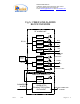
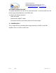
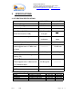
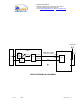
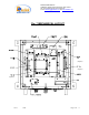
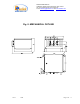
Table Of Contents
- FiberLink(
- BI-DIRECTIONAL AMPLIFIER
- MW-FBDA-PCS-xxx-50W
- _
- The duplexer serves to frequency separate uplink signals from downlink signals. The duplexer has sharp out of band attenuation for better isolation between the receiving and transmitting paths and for better rejection of interfering signal in the air.
- The uplink pre-amplifier is a low noise, 45dB gain unit. The amplifier contains AGC control circuitry. When a high power signal is received the automatic level control detects it and reduces the gain so that the output power of the amplifier is constant.
- The LED on the amplifier illuminates when the power output of the amplifier exceeds the AGC power set limit (when the AGC is either ON or OFF).
- The Switch on the RF amplifier enables the AGC function. If the AGC is disabled then the amplifier gives maximum gain for any input.
- The AGC level is factory set to 0 dBm and AGC is set to ON, to prevent high power damage at the Rfiber+ input.
- This is the downlink power amplifier. It can driv
- The FBDA monitor performs the following functions:
- a) Monitors the DC supply voltage of the FBDA. The fault LED illuminates when the voltage is beyond the specified limits.
- b) Monitors the current to each active element and the internal fan. If the current is below or above the specified limits then a LED illuminates.
- c) Monitor the optical receive signal using alarm output of the optical transceiver.
- d) Monitors the Thermostat for high temperature alarm.
- e\) Provides automatic alarm function. Whenever
- e) Provides self test for the alarm functions. The pushbutton switch on the Monitor unit turns on all the alarm LEDs and initiates the summarized alarm.
- 2.6 POWER CONNECTION UNIT
- The power distribution unit acts as DC connection panel. It receives power from the power supply and distributes it to the FBDA units.
- It contains the following functions:
- Power ON switch
- Downlink AGC ON/OFF switch
- Fuse and for the DC power coming from the AC power supply.
- 2.7 POWER SUPPLY
- This is a high efficiency switching power supply providing +28 VDC for the 50W amplifier, and a +15 VDC for other units.
- In order to satisfy the FCC RF exposure requirements, you must ensure that the installation complies with the following:
- The antenna is connected via cable that has typical 1~10 dB attenuation (depends on the length of the cable) to the FBDA MOBILE port.
- There are two applications: Outdoor and Indoor.
- In the case of Outdoor the type of antenna is omnidirectional (isotropic) with 0 to 2 dBi typical gain, or wide beam with up to 3 dBi gain, and is installed on a mast to cover shadowed, outdoor, area. This antenna must be installed to provide a minimum
- In the case of Indoor coverage the power is split to several, omnidirectional (isotropic) antenna with 0 to 2 dBi typical gain, and distributes to different indoor areas (in building floors, tunnels, basements, parking lots, shopping centers etc.). T
- Less separation is needed if the power is divided into more than 5 antenna covering many floors or areas.
- Fig. 7:MECHANICAL LAYOUT
- Limited Warranty

Dekolink WIRELESS Ltd.
16 Bazel St. Qiryat-Arieh Petah-Tikva, Israel, 49510
Tel- 972-3-9180-180 Fax-972-3- 190-9180
e-mail: marketing@dekolink.com
web www.dekolink.com
3 SPECIFICATIONS:
3.1 RF SECTION SPECIFICATIONS
Uplink (RX) Downlink (TX)
Frequency Range See Table See Table
Passband Gain @ min attenuation 45 dB Nominal 45 dB Nominal
Passband Ripple ± 1.0 dB typical ± 1.0 dB typical
Noise Figure @+25
°
C
(optical loss less than 3 dB)
6.0 dB max @
max gain
N.A.
Manual Attenuation Range 0 to 16 dB
continuous
30 dB in 2 db
steps
Down-Link Output Composite Power ----------------- +40 dBm typ.
Down-Link 3
rd
Order Intermodulation
Products @two tones +37 dBm each
at Output
---------------
50 dBc min
AGC Range 30 dB typ 10 dB typ
Power Output at AGC Setting
(Factory Set)
0 ± 1 dBm +40 ± 1 dBm
Up-Link 3
rd
Order Intermodulation
Products @two tones -3 dBm each at
F/O Transmitter Input
55 dBc typical
---------------
Impedance Level 50 Ohms
VSWR 1.5 : 1 max
System Frequency Range
SYSTEM TYPE MODEL No DOWN-LINK UP-LINK
Block B MW-FBDA-PCS-B-50W 1950-1965 1870-1885
Block D+B+E MW-FBDA-PCS-DE-50W 1945-1970 1865-1890
Block B+E+F MW-FBDA-PCS-BF-50W 1950-1975 1870-1895
Block D+B+E+F MW-FBDA-PCS-DF-50W 1945-1975 1865-1895
Rev1 12/03 Page 11 of 17