
User Manual
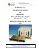
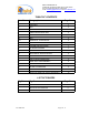
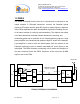
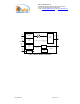
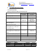
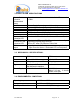
Table Of Contents
- For
- High Power
- Fiber-optic Repeater System
- (MW-FBDA-PCS-xxx-50W)
- & FiberopticBase Interface Unit
- (FBIU)
- _
- The FBDA is installed near the area to be covered and is connected to the mobile antenna. A Fiberoptic transceiver converts the Downlink optical signals to RF signals and the uplink RF signals to optical signals. A duplexer in the FBDA separates the upli
- of the same antenna for receiving and transmitting. The duplexer has sharp out of band attenuation for better isolation between the receiving and
- transmitting paths and for reduction of out of band interfering signals. A high power amplifier in the downlink path produces high RF power to the antenna. A pre-amplifier is used to drive the uplink signals from the antenna to the Fiberoptic transceiver
- Limited Warranty

Dekolink WIRELESS Ltd.
16 Bazel St. Qiryat-Arieh Petah-Tikva, Israel, 49510
Tel- 972-3-9180-180 Fax-972-3- 190-9180
e-mail: marketing@dekolink.com
web www.dekolink.com
3 . SYSTEM SPECIFICATIONS:
3.1 RF SPECIFICATIONS
(optical loss adjusted to 0dBm, all attenuators 30 dB)
Uplink (RX) Downlink (TX)
Frequency Range
Per system Per system
Passband Gain @ min attenuation 16 dB Nom. 10dB Nom.
Passband Ripple ± 1.0 dB typical ± 1.0 dB typical
Manual Attenuation Range 0 to 16 db cont.
(FBDA side)
0-10 dB in 1dB steps
(FBIU side)
0-30 dB in 2dB steps
(FBDA side)
Noise Figure @+25
°
C
(optical loss less than 3 dB)
6.0 dB max N.A.
Up-Link 3
rd
Order Intermodulation
Products @two tones -3 dBm each
at FBIU Rfiber Output
55 dBc typical N.A.
Down-Link 3
rd
Order Intermodulation
Products @two tones +37 dBm each at
Output
---------------
50 dBc min.
AGC Power Level(Factory Set) 0 ± 1.0 dBm nom. 40±1 dBm
AGC Range 30 dB min 10
Impedance Level 50 Ohms
VSWR In 1.5 : 1 typ
VSWR Out 2.0 : 1 typ
System Frequency Range
SYSTEM TYPE MODEL No DOWN-LINK UP-LINK
Block B MW-FBDA-PCS-B-50W 1950-1965 1870-1885
Block D+B+E MW-FBDA-PCS-DE-50W 1945-1970 1865-1890
Block B+E+F MW-FBDA-PCS-BF-50W 1950-1975 1870-1895
Block D+B+E+F MW-FBDA-PCS-DF-50W 1945-1975 1865-1895
FO-50W SYS Page 7 of 12