
User Manual
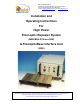
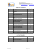
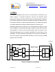
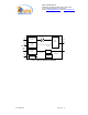
Table Of Contents
- For
- High Power
- Fiber-optic Repeater System
- (MW-FBDA-PCS-xxx-50W)
- & FiberopticBase Interface Unit
- (FBIU)
- _
- The FBDA is installed near the area to be covered and is connected to the mobile antenna. A Fiberoptic transceiver converts the Downlink optical signals to RF signals and the uplink RF signals to optical signals. A duplexer in the FBDA separates the upli
- of the same antenna for receiving and transmitting. The duplexer has sharp out of band attenuation for better isolation between the receiving and
- transmitting paths and for reduction of out of band interfering signals. A high power amplifier in the downlink path produces high RF power to the antenna. A pre-amplifier is used to drive the uplink signals from the antenna to the Fiberoptic transceiver
- Limited Warranty

Dekolink WIRELESS Ltd.
16 Bazel St. Qiryat-Arieh Petah-Tikva, Israel, 49510
Tel- 972-3-9180-180 Fax-972-3- 190-9180
e-mail: marketing@dekolink.com
web www.dekolink.com
2. SUBSYSTEM DESCRIPTION:
2.1 FBDA
Refer to installation and operation instructions for
MW-FBDA-PCS-xxx-50W
2.2 FBIU
The FBIU is the BTS interface of the system. It contains one Fiberoptic
transceiver and attenuators for uplink and downlink paths and power supply.
2.2.1 Fiberoptic transceiver
The Fiberoptic transceiver converts the signal form RF to optical in the
downlink direction and from optical signal to RF in the uplink direction.
2.2.2 Attenuators
Assuming that the output power of BTS is +30dBm, a 30 dB high power
external attenuator is required. In practice, more attenuation can be added
for different system setting.
For the RX path a separate 30 dB attenuator is connected at the F/O unit
output.
FO-50W SYS Page 5 of 12