
User Manual
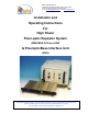
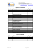
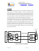
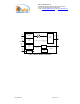
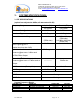
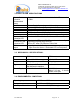
Table Of Contents
- For
- High Power
- Fiber-optic Repeater System
- (MW-FBDA-PCS-xxx-50W)
- & FiberopticBase Interface Unit
- (FBIU)
- _
- The FBDA is installed near the area to be covered and is connected to the mobile antenna. A Fiberoptic transceiver converts the Downlink optical signals to RF signals and the uplink RF signals to optical signals. A duplexer in the FBDA separates the upli
- of the same antenna for receiving and transmitting. The duplexer has sharp out of band attenuation for better isolation between the receiving and
- transmitting paths and for reduction of out of band interfering signals. A high power amplifier in the downlink path produces high RF power to the antenna. A pre-amplifier is used to drive the uplink signals from the antenna to the Fiberoptic transceiver
- Limited Warranty

Dekolink WIRELESS Ltd.
16 Bazel St. Qiryat-Arieh Petah-Tikva, Israel, 49510
Tel- 972-3-9180-180 Fax-972-3- 190-9180
e-mail: marketing@dekolink.com
web www.dekolink.com
TABLE OF CONTENTS
Para No. Paragraph Page No.
1. OVERVIEW 3
1.1 FBIU 3
1.2 FBDA 4
2. SUBSYSTEM DESCRIPTION 5
2.1 FBDA 5
2.2 FBIU 5
2.2.1 FIBEROPTIC TRANSCEIVER 5
2.2.2 ATTENUATORS 5
3 SYSTEM SPECIFICATIONS 7
3.1 RF SPECIFICATIONS 7
3.2 FBDA ALARM SPECIFICATIONS 8
3.3 MECHANICAL SPECIFICATIONS 8
3.4 ENVIRONMENTAL CONDITIONS 8
4 INSTALLATION PROCEDURE 9
4.1 FIBER OPTIC LINK ASSEMBLY 9
4.2 DOWNLINK CALLIBRATION 9
4.3 UPLINK CALLIBRATION 9
4.4 SYSTEM ASSEMBLY 10
DEKOLINK WIRELESS LIMITED WARRANTY 12
LIST OF FIGURES
Fig No. Fig. Name Page No.
1 FBDA SYSTEM BLOCK DIAGRAM 4
2 FBIU RF BLOCK DIAGRAM 6
3 FBIU MECHANICAL LAYOUT 11
FO-50W SYS Page 2 of 12