
User's Manual
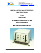
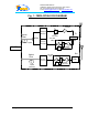
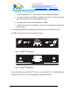
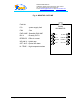
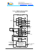
Table Of Contents
- FiberLink(
- BI-DIRECTIONAL AMPLIFIER
- WITH DIVERSITY
- MW-FBDA-800AB-50W-DIV
- _
- The duplexer serves to frequency separate uplink signals from downlink signals. The duplexer has sharp out of band attenuation for better isolation between the receiving and transmitting paths and for better rejection of interfering signal in the air. In
- The uplink amplifier is a low noise, 45dB gain unit. The amplifier contains AGC control circuitry. When a high power signal is received the automatic level control detects it and reduces the gain so that the output power of the amplifier is constant. The
- The LED on the amplifier illuminates when the power output of the amplifier exceeds the AGC power set limit (when the AGC is either ON or OFF).
- The Switch on the RF amplifier enables the AGC function. If the AGC is disabled then the amplifier gives maximum gain for any input.
- The AGC level is factory set to 0 dBm and AGC is set to ON, to prevent high power damage at the Rfiber+ input.
- The FBDA monitor performs the following functions:
- a) Monitors the DC supply voltage of the FBDA. The fault LED illuminates when the voltage is beyond the specified limits.
- b) Monitors the current to each active element and the internal fan. If the current is below or above the specified limits then a LED illuminates.
- c) Monitor the optical receive signal using alarm output of the optical transceiver.
- d) Monitors the Thermostat for high temperature alarm.
- e\) Provides automatic alarm function. Whenever
- e) Provides self test for the alarm functions. The pushbutton switch on the Monitor unit turns on all the alarm LEDs and initiates the summarized alarm.
- 2.7 POWER DISTRIBUTION UNIT
- The power distribution unit acts as DC connection panel. It receives power from the power supply and distributes it to the FBDA units.
- It contains the following functions:
- Fuse and for the DC power coming from the AC power supply.
- Current sampler for the high power 50 Watt amplifier.
- distribution strip for various units.
- 2.8 POWER SUPPLYS
- This is a high efficiency switching power supply providing +28 VDC for the 50W amplifier, and a +13.5 VDC for other units.
- In order to satisfy the FCC RF exposure requirements, you must ensure that the installation complies with the following:
- The antenna is connected via cable that has typical 1~10 dB attenuation (depends on the length of the cable) to the FBDA MOBILE port. In most cases, indoor or outdoor, the antenna is omnidirectional (isotropic), or wide beam, with 0 to 3 dBi typical
- For indoor applications the output power can be distributed to several antennas.
- When 4 antennas (or more) are used, the indoor antenna must be installed to provide a minimum separation distance of 0.3 m (30 cm) from persons within the area.
- Fig. 7:MECHANICAL LAYOUT

Dekolink WIRELESS Ltd.
16 Bazel St. Qiryat-Arieh Petah-Tikva, Israel, 49510
Tel- 972-3-9180-180 Fax-972-3- 190-9180
e-mail: marketing@decolink.com
web www.decolink.com
2. COMPONENTS DESCRIPTION:
2.1 DUPLEXER(x2)
The duplexer serves to frequency separate uplink signals from downlink signals. The
duplexer has sharp out of band attenuation for better isolation between the receiving
and transmitting paths and for better rejection of interfering signal in the air. In the
Diversity path only the Rx part of the duplexer is used.
2.2 UPLINK AMPLIFIER(both Rx pathes)
The uplink amplifier is a low noise, 45dB gain unit. The amplifier contains AGC control
circuitry. When a high power signal is received the automatic level control detects it
and reduces the gain so that the output power of the amplifier is constant. The AGC
function limits the signal at the Fiberoptic transmitter input when high power signals
are received while keeping high gain when low power signals are received.
The LED on the amplifier illuminates when the power output of the amplifier exceeds
the AGC power set limit (when the AGC is either ON or OFF).
The Switch on the RF amplifier enables the AGC function. If the AGC is disabled then
the amplifier gives maximum gain for any input.
The AGC level is factory set to 0 dBm and AGC is set to ON, to prevent high power
damage at the Rfiber+ input.
2.3 50 WATT DOWNLINK POWER AMPLIFIER
This is the downlink power amplifier. It can drive 40 dBm composite power to the
MOBILE antenna. A thermostat attatched to this amplifier turns on TEMP alarm when
the temperature exceeds 80° C.
2.4 Fiberoptic to RF transceiver
The RFiber+
TM
product is a transceiver that includes a transmitter and receiver unit.
The transmitter converts the RF signals into light wave signals, which are then sent
over fiberoptic cables. The receiver converts light wave signals back to RF
The model in use is a wide band product in the 0.08-1 GHz frequency range and it
includes a WDM module to enable use of one fiber for Tx and Rx signals.
Page 5 of 15 FBDA-800AB-50wDIV-INSTL1.doc