
Operating Instructions


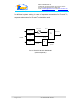
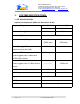
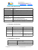

Table Of Contents
- FOR
- CELLULAR A+B
- Fiber-optic REPEATER SYSTEM
- 50W WITH DIVERSITY
- _
- The FBDA is installed near the area to be covered and is connected to the mobile antenna. A Fiberoptic transceiver converts the Downlink optical signals to RF signals and the uplink RF signals to optical signals. A duplexer in the FBDA separates the upli
- of the same antenna for receiving and transmitting. The duplexer has sharp out of band attenuation for better isolation between the receiving and
- transmitting paths and for reduction of out of band interfering signals. A high power amplifier in the downlink path produces high RF power to the antenna. A LNA (low noise amplifier) is used to drive the uplink signals from the antenna to the Fiberopt
- For diversity applications the uplink path is duplicated using separate antenna, filter, LNA and Fiberoptic transmitter.
- Please refer to installation and operation instructions for FBDA-800AB-50W-DIV
- Fig. 3: FBIU MECHANICAL LAYOUT

Dekolink WIRELESS Ltd.
16 Bazel St. Qiryat-Arieh Petah-Tikva, Israel, 49510
Tel- 972-3-9180-180 Fax-972-3- 190-9180
e-mail: marketing@decolink.com
web www.decolink.com
for different system setting. In case of separate connections for Rx and Tx ,
separate attenuators for Rx and Tx should be used.
TO BTS
FIG 2: FBIU RF BLOCK DIAGRAM
(without duplexer)
High pwr ATTN.
F/O+
WDM
RF IN
RF Out
optical in/out
optical in
ATTN.
(MAX. 0dBm)
F/O
RF Out
ATTN.
VAR. ATTN.
Page
6 of
6
FO-800AB-50W SYS.doc