
User's Manual

Page 11 of 21
IDEN Digital Repeater Installation
Manual
8 Installation of the Repeater in Lab.
NOTE! In case that Antennas are not connected, terminate the Base & Mobile marked
connectors with a 30dB attenuator, in order to prevent damage (by a regressing signal) to
protect the Test equipment.
The attenuators power rating should be at least 50W at the Mobile marked repeater’s
terminal, and 10W at Base marked repeater’s terminal.
- Connect power supply. A supplied voltage in the range of 90 to 260VAC should be
connected to the repeater’s AC power connector.
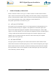
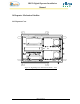
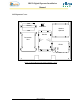
- Inject to the repeater’s Downlink route terminal (Base connector), RF Signal from the
connected RF Generator, and a Spectrum Analyzer, to the repeater’s Mobile terminal,
and test the repeater RF performance (see test set up diagram below).
S.Analyzer
RF IN
30dB
PED
30dB
PED
Signal
Generator
RF
OUT
RF Cable
RF Cable
Dekolink
Repeater
Base Mobile
Figure 6: Repeater Downlink rout RF performance test set up.
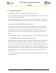
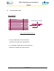
- Test the Repeaters’ Uplink route, by connecting RF Signal Generator to the repeater’s Mobile
marked terminal and a Spectrum Analyzer to the Base marked terminal (see test set up diagram
below).
S.Analyzer
RF IN
30dB
PED
30dB
PED
Signal
Generator
RF
OUT
RF Cable
RF Cable
Dekolink
Repeater
Base Mobile
Figure 7: Repeater Uplink rout RF performance test set up