IDEN Digital Repeater Installation Manual IDEN Digital Repeater Installation Manual MW-DR-800-50W90B DekoLink WireLess Proprietary and Confidential Information. Copying, Distribution, and Disclosure are Prohibited without Express Authorization from DekoLink WireLess Company.
IDEN Digital Repeater Installation Manual 1 Table of Contents 1 Table of Contents 2 2 Table Of Figures. 3 3 Introduction. 4 3.1 3.2 Computer Program. .................................................................................................4 Programmable Modules ..........................................................................................4 4 Electrical Specifications 5 5 RF Block Diagram 7 6 System Components description. 8 7 Repeater Monitor And Control 7.
IDEN Digital Repeater Installation Manual 2 Table Of Figures. Figure 1: Digital Repeater RF Block Diagram............................................................................... 7 Figure 2: Digital Repeater Layout.................................................................................................. 8 Figure 3: Remote Alarm and Control unit – zoom-out ................................................................. 10 Figure 4: Local Mode Figure 5: Remote Mode ..........................
IDEN Digital Repeater Installation Manual 3 Introduction. Dekolink Wireless channel selective repeaters employ digital processing techniques to attain versatile programmable filter array. The input RF signal is sampled and converted to digital signals. The digital signal is filtered using fast parallel logic. Using digital processing techniques the system generates up to 8 (12 optional) separate, programmable and independent filters.
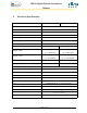
IDEN Digital Repeater Installation Manual 4 Electrical Specifications Frequency Range Downlink 851-866 MHz Pass band Gain @Min attenuation. Uplink Up to 100 dB Channel Bandwidth See Sample from Table Channel Setting Resolution 0.5 kHz Passband Ripple ± 2.5 dB max Channel Ripple ± 0.5 dB max Delay Ripple ± 250 nSec max Noise Figure @max gain 3rd Order Output Intercept Point 806-821 MHz 5.0 dB max +62 dBm typical +50 dBm typical 48 dBc typical 48 dBc typical @ 2.5 Watt/tone @ 0.
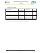
IDEN Digital Repeater Installation Manual Examples for filters capability: Filter Description 0.5 [dB] Bandwidth (min) Min Rejection Delay [uSec] (max) Single Channel @3Channel Spacing 25[KHz] 50[dB] @ Fc±87.5 KHz 25 Single Channel @2Channel Spacing* 25[KHz] 50[dB] @ Fc±62.5 KHz 32 Single Channel @1Channel Spacing 25[KHz] 50[dB] @ Fc±37.
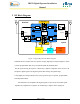
IDEN Digital Repeater Installation Manual 5 RF Block Diagram BASE ANT MOBILE ANT Digital Filters Downlink AGC LNA AGC AMP DownConverter UpConverter Micro controller Channeler Duplexer AGC AGC DownConverter UpConverter PA Power Monitor PA AGC AGC Duplexer Power Monitor AGC LNA AGC AMP Uplink Digital Filters Controller Interface Box Power Supply Figure 1: Digital Repeater RF Block Diagram.
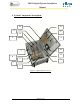
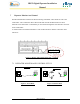
IDEN Digital Repeater Installation Manual 6 System Components description. 8 15 4 9 14 11 3 10 7 12 6 5 13 1 2 Figure 2: Digital Repeater Layout.
IDEN Digital Repeater Installation Manual Component Description: 1. Digital Filter Module for Downlink (include operation indication LED ) 2. Digital Filter Module for Uplink (include operation indication LED ) 3. Channler ( Dual Up/down Converter for Uplink & Downlink Paths). 4. Diplexer to donor Antenna. 5. Diplexer to mobile Antenna (High Power). 6. Coupler for Modem Antenna. 7. Isolator for Uplink Amplifier. 8. Connections Box (include Repeater ON/Off switch). 9. BDA Monitor unit.
IDEN Digital Repeater Installation Manual 7 Repeater Monitor And Control The BDA Monitor Box monitors the DC functioning of the BDA. These faults are sent to the Control Box. The Control Box detects these faults and controls the BDA functions. These functions can be monitored or controlled by an external PC through the serial interface connector on the Control Box. A cellular modem is installed in the BDA. This modem interfaces with the control box and a remote PC.
IDEN Digital Repeater Installation Manual 8 Installation of the Repeater in Lab. NOTE! In case that Antennas are not connected, terminate the Base & Mobile marked connectors with a 30dB attenuator, in order to prevent damage (by a regressing signal) to protect the Test equipment. The attenuators power rating should be at least 50W at the Mobile marked repeater’s terminal, and 10W at Base marked repeater’s terminal. - Connect power supply.
IDEN Digital Repeater Installation Manual 9 REPEATER (BDA) OPERATION The RF connection is made via two type “N” female connectors. The RF connector labeled “Base” must be connected to the antenna pointing to the base station; usually a rooftop antenna. The RF connection labeled “Mobile” must be connected to the antenna pointing into the area to be covered by the Repeater such as inside a building or outdoor shaded area. The repeater operates from 110V/220 VAC @ 2A. 9.
IDEN Digital Repeater Installation Manual 10 BDA INSTALLTION Install the BDA Repeater in a shielded, ventilated and easy to reach area. Use low loss cables to connect antennas to the BDA. Install the BDA close to the service area to improve output power and noise figure. The BDA Base/Donor connector port is connected to donor antenna, usually a Yagi antenna, while the BDA Mobile/Remote connector port is connected to a mobile antenna; outdoor indoor. 10.
IDEN Digital Repeater Installation Manual 10.3 ANTENNA ISOLATION For proper operation the isolation between these two antennas must be at least 10 dB higher than the BDA gain. Lower isolation would lead to high in-band ripple. Oscillations will build up when the isolation is lower than BDA gain. The isolation between the antennas is critical for high gain outdoor repeaters. To measure the isolation, inject a known signal into one antenna and measure the coupled output at the other antenna.
IDEN Digital Repeater Installation Manual 11 INSTALLATION STEPS 1. Install all antennas and connect them to the BDA inputs. 2. Set “MAX Gain” according to isolation (at least 15 dB lower) and available donor power. This allows the SAGC to smartly limit the output power of the BDA. Optional: The SAGC on the Downlink path guarantees constant downlink power (relative to cell traffic) when and if the Donor power changes. 3. Uplink will set ultimately according to the downlink gain. 4.
IDEN Digital Repeater Installation Manual 12 RF EXPOSURE WARNING In order to satisfy the FCC RF exposure requirements, you must ensure that the installation complies with the following: One antenna is connected via cable that has typical 1~10 dB attenuation (depends on the length of the cable) to the BDA base port. This antenna is installed outdoor and has very sharp beam (Yagi type or similar) pointed to the donor (BTS). This type of antenna has about 10dBi gain.
IDEN Digital Repeater Installation Manual 13 BDA MONITORING AND ALARMS The BDA monitors its functions and alarms are declared when necessary. Some of these alarms illuminate a red LED on the BDA monitor box. 13.1 LINK ALARMS (up link & down link) 13.1.1 Power Amplifier Uplink Forward power amplifier Current Alarm: Declared when the Power Amplifier current is above or below its specified limits.
IDEN Digital Repeater Installation Manual 14 Repeater Mechanical Outline. 14.1 Repeater Case.
IDEN Digital Repeater Installation Manual 14.2 Repeater Cover.
IDEN Digital Repeater Installation Manual 15 External Alarm Cable. Pinout Definition: A External Swith No.2 Green/White B Ground Black C Not Connected Alarm Connector on Cable H D Alarm Out from Monitor Unit (Also shorten to DC connector pin D) Black/White Alarm In from Monitor Unit (Also E shorten to DC connector pin B) Black/White F Ground Black G External Swith No.1 Gray H Ground Black EXT.
IDEN Digital Repeater Installation Manual 16 Dekolink Wireless Limited Warranty. Dekolink Wireless [Ltd.] (“Dekolink”), manufacturer of this product (the “Product”) warrants to the original purchaser (“Purchaser”) that the Product is free from defects in materials and workmanship for a term that ends on the earlier of twelve (12) months from the date of activation of the Product or fifteen (15) months from the date of shipment of the Product by Dekolink.