
User's Manual


PRODUCT MANUAL DEKO4078SD MULTI-CHANNEL SIGNAL BOOSTER DEKOLINK WIRELESS LTD.
Page 36 Proprietary Data P/N 300SC30031 Rev. 1.2
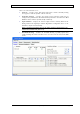
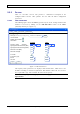
5.3.3.2 Filter Description
The following figure shows the Filters (description) tab of the
Settings
window. A
separate window is displayed for each of the 700 and 800 bands.
This window includes the Add/Edit Filter option and provides a description of the
type of filter(s) in use, their UL and DL center frequency, output power and gain.
After the filters have been configured the user can navigate to this screen in order to
view the filter characteristics (read only screen).
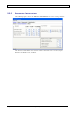
Figure 19. Filter Description
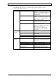
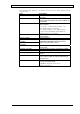
The following tables provide a description of the fields and buttons displayed in the
figure above.
Field Description
ID Filter ID Number
Select Checkbox for selecting filter to be edited
Enable
Provides indication on whether the filter is enabled or
not
Description
Description of selected filter type (see
4.2.3)
Channel Filter channel number - translation from frequency to
channel number
Center Frequency (MHz) DL/UL center frequency
Max Out Power (dBm) DL/UL Max composite output power settings
Max Gain (dB) DL/UL Max gain settings
Button Description Comments
Add/Edit Filter Used for adding a new filter or editing an
existing one
Delete Filter Used for removing a selected filter from the
list
Previous Used for navigating to previous screen
(filter parameters screen) of selected filter
when editing
It is recommended to
avoid using the scroll
bar and use the Next
and Previous buttons
Next Used for navigating to next screen
A
dd/Edit Filter button.