
User's Manual


PRODUCT MANUAL DEKO4078SD MULTI-CHANNEL SIGNAL BOOSTER DEKOLINK WIRELESS LTD.
P/N 300SC30031 Rev. 1.2 Proprietary Data Page 35
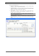
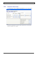
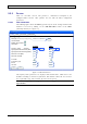
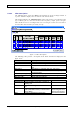
The following table provides a description of the parameter fields displayed in the
window above.
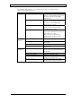
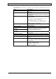
Field Description
Filter Type Combo box that provides a list of the available
filter types
Transmit Enable Enables filter operability. If this option is not
enable (check marked) the filter will be defined but
not operable.
Multiple Channel Enable Option for enabling/disabling (default: enable)
filter monitoring
For Setup – enables RSSI readings even
when channel is not transmitting
For wideband filters – if a wideband filter
is selected the monitoring option should be
disabled in order to save power.
AGC Enable Option for enabling and disabling Automatic Gain
Control feature
Frequency (MHz) Center Frequency
Signal Gate Threshold Level
low (dBm)
UL and DL RSSI thresholds (low and high) in the
Signal Gate Threshold fields determine the
range in which the filter is active
Signal Gate Threshold Level
high (dBm)
Max Power Level (dBm) This value limits the signal booster maximum
output power.
Max Gain Level (dB) This value limits the gain to a maximum of 90dB.
PL Enable Option for enabling and disabling PL
PL Frequency (Hz) Enables setting the PL frequency between 67 –
254 Hz
ID Tone Provides several options for generating a specific
tone in order to check the communication during
setup (see
6.1)
CW Route Determines the type of signal generated for the ID
Tone by the signal booster
Normal – Signal is passed “as is”
Zero – No signal