
User's Manual


PRODUCT MANUAL DEKO4078SD MULTI-CHANNEL SIGNAL BOOSTER DEKOLINK WIRELESS LTD.
Page 34 Proprietary Data P/N 300SC30031 Rev. 1.2
5.3.3 FILTERS
There are two filter screens: One provides a summarized description of the
configured filters and the other provides the user with the filters’ configurable
parameters.
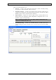
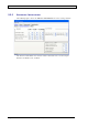
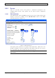
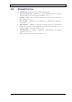
5.3.3.1 Filter Parameters
The following figure shows the Filters (parameters) tab of the
Settings
window. This
window is accessed by clicking on the Add/Edit filter button of the Filter
(700/800) window (see Figure 19).
UD2
700/800 Booster
700/800 Booster
General Filters
Settings Alarms Measurments Administration
Menu bar
Apply Cancel
12.5KHz, 15u, 61dB@25KHz
Uplink
Downlink
769.7000
Show
799.7000
Uplink
Transmit enable
Frequency (Mhz) / channel#
Signal gate Threshold level low (dBm)
Max Power Level (dBm)
Max Gain Level (dB)
-110
37
95
-110
27
95
Filter type
150
160
Multiple channel enable
Signal gate Threshold level high (dBm)
-100
-100
PL enable
PL frequency (Hz)
ID tone
36
36
Normal
Normal
AGC enable
(BW, Delay, Rejection @ spacing)
CW route
Normal
Normal
Figure 18. Filter Parameters
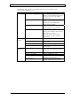
The majority of the parameters are displayed with default values, which can be user
modified according to customer requirements. This window enables the user to select
the required filter type and determine the DL center frequency.
Note: After configuring or modifying a parameter, click Apply to save the definition to the
signal booster.