
User's Manual

PRODUCT MANUAL DEKO4078SD MULTI-CHANNEL SIGNAL BOOSTER DEKOLINK WIRELESS LTD.
P/N 300SC30031 Rev. 1.2 Proprietary Data Page 27
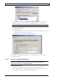
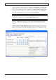
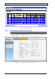
Figure 15. Add/Edit Filter Window
The filter parameters are displayed with default values, however these may be
modified. Note that the filter PL enable parameter is
disabled
by default.
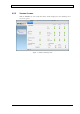
3. Select the required filter from the Filter Type field drop-down list according to
the following:
• Bandwidth
• Delay
• Rejection at spacing
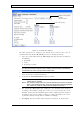
Note: The Filter screen includes a Show button that provides several display types
(i.e. filter pass band and rejection plots), enabling viewing the filter properties and
characteristics to ensure a proper selection of the filter.
4. Define the DL center frequency in the Frequency field. The corresponding UL
center frequency is automatically defined.
5. Verify that the Transmit Enable checkbox is enabled.
Note 1: If the Transmit Enable parameter is not enabled then the filter will be
defined but not operable.
Note 2: The maximum output power of a channel depends on the number of defined
filters. Upon defining new filter, the system will provide a warning regarding
the new limit of maximum output power available for each filter.
6. The default filter Max Gain value displayed is the Maximum Gain calculated
according to the isolation settings (see section
4.2.1 step 2). This value can be
modified, however the filter Maximum Gain cannot be higher than that calculated
according to the booster isolation settings. If a higher maximum gain value is
required the isolation settings must be modified accordingly.
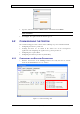
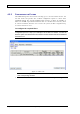
7. Click Apply. The selected filter and description are displayed, as shown below.
Click to view graph
of filter
characteristics.
Center Frequency