
User's Manual

PRODUCT MANUAL DEKO4078SD MULTI-CHANNEL SIGNAL BOOSTER DEKOLINK WIRELESS LTD.
Page 24 Proprietary Data P/N 300SC30031 Rev. 1.2
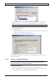
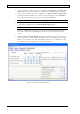
2. In the
Isolation Settings
field area, determine the Isolation and Back off
isolation parameters. The application calculates the Max gain (dB) accordingly.
3. In the
Input Window
field area, configure the Input window High Limit
parameter which determines the signal boosters’ signal range. The Low limit is
automatically determined according to the configured
High limit
.
Note: The attack and release times can be configured. See Step 5.
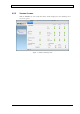
4. Determine the number of filters to be allocated for each band. Select the
required filter configuration in the Downlink Routing field area.
Note: The default setting is 12 Filter for 700MHz, 12 Filters for 800MHz.
The filter configuration selected here determines the maximum number of filters
that can be added when configuring the filters for the 700 and 800 bands (see
4.2.3).
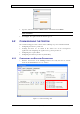
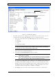
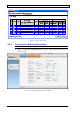
5. Click the Advanced Installation window and define the parameters displayed
in the
General
(i.e.
in Path offset
) and
Marker Tone, PL Mode
(For analog – FM)
field areas. In addition, the
Attack
and
Release
times can be configured for the
input signal range determined in the
General Settings
tab.
Figure 12. Advanced Installation Tab