
User's Manual

PRODUCT MANUAL DEKO4078SD MULTI-CHANNEL SIGNAL BOOSTER DEKOLINK WIRELESS LTD.
P/N 300SC30031 Rev. 1.2 Proprietary Data Page 15
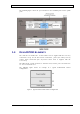
1.4.3 POWER SUPPLY INTERFACES
The power supply feeds the power DIRECTLY to the Main unit and is provided with 1
to 3 installed (power) modules (for redundancy) which are preconfigured according
to the installation.
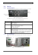
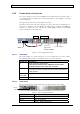
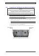
The figure below shows the Power Supply rear panel.
The figure below shows the Power Supply rear panel. Note that the dipswitches are
factory set according to the installation and should not be modified. The DB25 J1
connector is connected to the +V DC and –V DC (Ret) connectors from which
power is distributed to the Main unit.
Figure 6. Power Supply Rear Panel
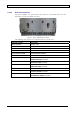
1.4.3.1 Rear Panel
The Power Supply rear panel connectors are accessed from the rear of the cabinet.
The following table provides a description of the rear panel connectors.
CONNECTOR DESCRIPTION
J1 25-pin connector. Output power.
If not already connected, the supplied accessory cable
should be connected to +V DC and –V DC Ret.
AC Main 110/220 AC power connections corresponding to the power
units. Each connector corresponds to the parallel internal power
supply module.
+V DC and
-V DC (Ret)
Connections to the Main unit
SW1 Not Applicable.
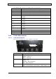
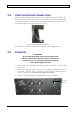
1.4.3.2 Front Panel
The Power Supply front panel contains the unit fans and three status LEDs.
Figure 7. Power Supply Front Panel
POWER SUPPLY LED DESCRIPTION
DC OK GREEN – NORMAL OPERATION
DC FAIL RED - MALFUNCTION
AC OK
G
REEN – NORMAL OPERATION
Status
LEDs
DB25 J1
Factory set
Dipswitches –
do not modify!
+V DC
-V DC (Ret)
To AC outlet(s)