
User's Manual

PRODUCT MANUAL DEKO4078SD MULTI-CHANNEL SIGNAL BOOSTER DEKOLINK WIRELESS LTD.
Page 12 Proprietary Data P/N 300SC30031 Rev. 1.2
1.4.1 MAIN UNIT
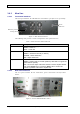
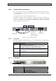
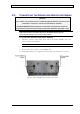
1.4.1.1 Front Panel Interfaces
The front panel includes the LED indicators and Ethernet port (for service personnel).
Figure 3. Main Unit Front Panel
The following table provides a brief description the front panel indicators.
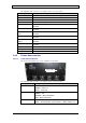
Table 3. Main Unit Front Panel Indicators
Status Indicator Description
Power On Main drawer power supply:
GREEN - Power On
GRAY – Power Off
Status Main drawer status:
GREEN – All statuses are OK (no alarms)
ORANGE – Minor malfunction
RED – Major malfunction
System Service status:
GREEN - System ready for normal operation (if this LED is not green the
system will not operate).
RED – No service. Major malfunction at Main or Power Amplifier drawer
Note: If the System LED is red but the Status LED is not then this
indicates a problem at the Power Amplifier unit.
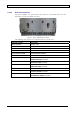
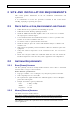
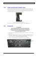
1.4.1.2 Rear Panel Interfaces
The rear panel contains the RF connections, power connections and dry-contact
alarms.
Figure 4. 700/800 DMSB UHF Rear Panel
Status
indicators
Ethernet port fo
r
mana
g
emen
t