
User Manual
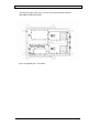
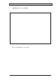
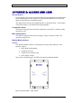
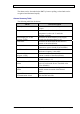
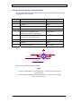
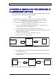
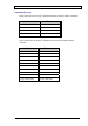
Table Of Contents
- INTRODUCTION
- FUNCTIONAL DESCRIPTION
- DESCRIPTION
- INSTALLATION
- REPEATER MANAGEMENT TOOL (RMT)
- OPERATION
- MAINTENANCE AND TROUBLESHOOTING
- APPENDIX A: MECHANICAL OUTLINE
- APPENDIX B: ALARMS AND LEDS
- APPENDIX C: INSTALLING THE REPEATER IN A LABORATORY SETTING
- APPENDIX D: MODEM INSTALLATION (OPTION)
- APPENDIX E: DEKOLINK WIRELESS LIMITED WARRANTY

DIGITAL REPEATER PRODUCT MANUAL DEKOLINK WIRELESS LTD.
Connector Pin-out
Serial Cable Pin-out for Local Communication between the PC and the Controller:
PC Pinout CB Pinout
2 3
3 2
5 5
D-Type 9 Pin female D-Type 9 Pin female
Serial Cable Pinout for Remote Communication between the Modem and the
Controller:
DCE Modem DTE Controller
1 1
2 2
3 3
4 4
5 5
6 6
7 7
8 8
9 9
D-Type 9 Pin female D-Type 9 Pin male
Page 38 Proprietary Data Pub. 302-2004 Rev. 2.0