
User Manual
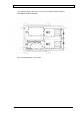

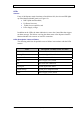
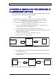
Table Of Contents
- INTRODUCTION
- FUNCTIONAL DESCRIPTION
- DESCRIPTION
- INSTALLATION
- REPEATER MANAGEMENT TOOL (RMT)
- OPERATION
- MAINTENANCE AND TROUBLESHOOTING
- APPENDIX A: MECHANICAL OUTLINE
- APPENDIX B: ALARMS AND LEDS
- APPENDIX C: INSTALLING THE REPEATER IN A LABORATORY SETTING
- APPENDIX D: MODEM INSTALLATION (OPTION)
- APPENDIX E: DEKOLINK WIRELESS LIMITED WARRANTY

DIGITAL REPEATER PRODUCT MANUAL DEKOLINK WIRELESS LTD.
APPENDIX C: INSTALLING THE REPEATER IN
A LABORATORY SETTING
If you want to test the performance of the repeater prior to actually installing it in the
field, you can do so in a laboratory setting as follows:
Note
In the event that the antennas are not connected, terminate the Base and Mobile
connectors with a 30 dB attenuator or 50 Ohm load.
This will prevent a regressing
signal from damaging the test equipment.
Use 30db attenuators with a power rating of at least 50W at the Mobile connector
and at least 10W at the Base connector.
Connect a Power Supply voltage (90 to 260 VAC) to the Repeater’s AC
connector (refer to the test diagram below).
•
•
•
•
•
Connect an RF Generator to the Repeater’s Base connector
Inject an RF Signal from the connected RF Generator to the downlink route
through the Base connector.
Connect a Spectrum Analyzer to the Mobile connector.
Test the repeater’s RF performance.
S.Analyzer
RF IN
30dB
Attenuator
30dB
Attenuator
Signal
Generator
RF
OUT
RF Cable
RF Cable
Dekolink
Repeater
Base Mobile
Figure 14: Repeater Downlink Route RF Performance Test Setup
Test the Repeater’s Uplink route by connecting the RF Signal Generator to
the Mobile connector
•
• Connect a Spectrum Analyzer to the Base connector (refer to the test setup
diagram below).
S.Analyzer
RF IN
30dB
Attenuator
30dB
Attenuator
Signal
Generator
RF
OUT
RF Cable
RF Cable
Dekolink
Repeater
Base Mobile
Figure 15: Repeater Uplink Route RF Performance Test Setup
Page 36 Proprietary Data Pub. 302-2004 Rev. 2.0