
User Manual
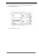
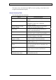
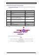
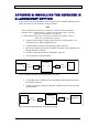
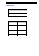
Table Of Contents
- INTRODUCTION
- FUNCTIONAL DESCRIPTION
- DESCRIPTION
- INSTALLATION
- REPEATER MANAGEMENT TOOL (RMT)
- OPERATION
- MAINTENANCE AND TROUBLESHOOTING
- APPENDIX A: MECHANICAL OUTLINE
- APPENDIX B: ALARMS AND LEDS
- APPENDIX C: INSTALLING THE REPEATER IN A LABORATORY SETTING
- APPENDIX D: MODEM INSTALLATION (OPTION)
- APPENDIX E: DEKOLINK WIRELESS LIMITED WARRANTY

DEKOLINK WIRELESS LTD. PRODUCT MANUAL DIGITAL REPEATER
LEDs
General
If any of the Repeater major functions as listed below fails, the relevant LED lights
up in the Monitor Module panel (see Figure 12):
DDF Uplink and Downlink, •
•
•
•
Up/Down Converter,
Uplink Power Amplifier, and
Power Supply voltage.
In addition to the LEDs, the alarm indication is sent to the Control Box that triggers
an alarm message. This allows receiving the alarm status of the Repeater from the
Monitor Module with a remote or local PC connection.
LEDs Description / Cause of Failure
The following table lists the probable cause of failure in accordance with the LEDs
statuses.
LED Description / Probable Cause of Failure
NC Not in use (not connected)
DL Dig Fil. Downlink digital filter failed
Converter Curr Channeler current failed
+9V Power supply (+9V) failed
NC Not in use (not connected)
UL Dig Fil. Uplink digital filter failed
UP PWR Amp. Uplink power amplifier failed
+28V Power supply (+28V) failed
Pub. 302-2004 Rev. 2.0 Proprietary Data Page 35