
User Manual
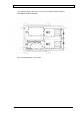
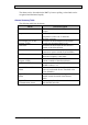
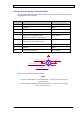
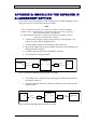
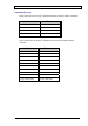
Table Of Contents
- INTRODUCTION
- FUNCTIONAL DESCRIPTION
- DESCRIPTION
- INSTALLATION
- REPEATER MANAGEMENT TOOL (RMT)
- OPERATION
- MAINTENANCE AND TROUBLESHOOTING
- APPENDIX A: MECHANICAL OUTLINE
- APPENDIX B: ALARMS AND LEDS
- APPENDIX C: INSTALLING THE REPEATER IN A LABORATORY SETTING
- APPENDIX D: MODEM INSTALLATION (OPTION)
- APPENDIX E: DEKOLINK WIRELESS LIMITED WARRANTY

DIGITAL REPEATER PRODUCT MANUAL DEKOLINK WIRELESS LTD.
External Alarms Connector Pinout Definition
The following table details the pinout definition of the External Connector located in
the gland plate of the repeater.
Letter Description Color Code
A External Switch No.2 Green/White
B Ground Black
C Not Connected N/A
D N/A N/A
E Alarm Out from Monitor Unit
(shortened to the DC connector pin)
Black/White
F Alarm In from Monitor Unit
(shortened to DC connector pin)
Black/White
G External Switch No.1 Gray
H Ground Black
A External Switch No.2 Green/White
G
F
E
D
C
B
A
H
EXT. Sw itc h 2
A
larm Out (from Monitor_15)
EXT. Sw itc h 2
A
la r m In ( fro m Mo n ito r_2 )
Figure 13: External Alarms Connector – Pinout
Notes
1. Use Gray and Black Wires for External Alarm 1 (Open/Close according to the
connected device).
2. Use Green/White and Black Wires for External Alarm 2 (Open/Close according
to the connected device).
Page 34 Proprietary Data Pub. 302-2004 Rev. 2.0