
User Manual
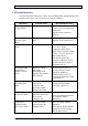
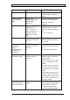
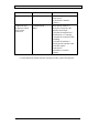
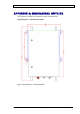
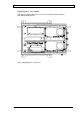
Table Of Contents
- INTRODUCTION
- FUNCTIONAL DESCRIPTION
- DESCRIPTION
- INSTALLATION
- REPEATER MANAGEMENT TOOL (RMT)
- OPERATION
- MAINTENANCE AND TROUBLESHOOTING
- APPENDIX A: MECHANICAL OUTLINE
- APPENDIX B: ALARMS AND LEDS
- APPENDIX C: INSTALLING THE REPEATER IN A LABORATORY SETTING
- APPENDIX D: MODEM INSTALLATION (OPTION)
- APPENDIX E: DEKOLINK WIRELESS LIMITED WARRANTY

DIGITAL REPEATER PRODUCT MANUAL DEKOLINK WIRELESS LTD.
7.5 TROUBLESHOOTING
The following table summarizes various error/warning alarms and indications, their
possible cause, and a course of action to correct the problem.
Indication Probable Cause Recommended Action
Power Supply
Voltage alarm
Supply voltage fault Check if the temperature alarm
is active. If so, see temperature
alarm below.
Turn the power off and on
again (*).
Power Amplifier
Uplink Current
alarm
Power Amplifier
Fault
Mute the Uplink Power
amplifier. Turn it back on (*).
Channeler Current
alarm
Channeler failed Check if a temperature alarm is
active. If so, see the
Temperature alarm below.
Check if the Lock Detect alarm
is active. If so, see the Lock
Detect alarm below.
Decrease the gain of the
Repeater to minimum, check
the alarm, and turn it back to
Maximum Gain (*).
Downlink/Uplink
Digital Filter
module’s current
alarm
High/Low current
fault in the
Downlink/Uplink
Digital Filter modules
and in the fan
Reset the Digital Filter by
pressing the Reset button.
Change the number of
channels that are active to
minimum and then turn it back
to maximum (*).
Downlink/Uplink
Communication
alarm
The communication
between the
Controller and
Downlink/ Uplink
Digital Filter failed
Reset the Digital Filter unit by
pressing the Reset button.
Reboot the repeater (*).
Downlink/Uplink
Lock Detect alarm
Faulty status of the
Phased Locked Loop
(PLL) in the
Channeler unit
Reboot the Repeater.
Check the connection between
the Controller and the
Channeler (*).
FWD Power
Amplifier alarm
(this is not a fault)
Composite output
power is below the
threshold value
Check the Donor antenna
connection.
Check that the Donor antenna
alignment is in line of sight
with the Base station.
Page 24 Proprietary Data Pub. 302-2004 Rev. 2.0