
User Manual
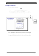
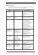
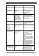
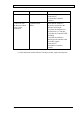
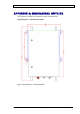
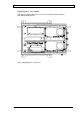
Table Of Contents
- INTRODUCTION
- FUNCTIONAL DESCRIPTION
- DESCRIPTION
- INSTALLATION
- REPEATER MANAGEMENT TOOL (RMT)
- OPERATION
- MAINTENANCE AND TROUBLESHOOTING
- APPENDIX A: MECHANICAL OUTLINE
- APPENDIX B: ALARMS AND LEDS
- APPENDIX C: INSTALLING THE REPEATER IN A LABORATORY SETTING
- APPENDIX D: MODEM INSTALLATION (OPTION)
- APPENDIX E: DEKOLINK WIRELESS LIMITED WARRANTY

DEKOLINK WIRELESS LTD. PRODUCT MANUAL DIGITAL REPEATER
7. MAINTENANCE AND TROUBLESHOOTING
7.1 GENERAL
This section provides the maintenance and troubleshooting procedures for the Digital
Repeater.
7.2 PERIODIC MAINTENANCE
There is no periodic maintenance required for the Digital Repeater. As long as it is
installed in a shaded area and not subject to extreme temperatures, it will provide long
term, carefree operation.
7.3 VISUAL INSPECTION
Note
Refer to Appendix b – Alarms and LEDs.
Check the following normal LEDs status inside the repeater:
During normal operation, all LEDs are off. •
• The LEDs should be checked 10 seconds after setting the Repeater on.
Their status should be as described below.
7.3.1 Monitor Module
All LEDs in this module are off.
These LEDs indicate faults in the Repeater and the status of some of them is also
displayed in the RMT main screen.
7.3.2 Controller Module
Ten seconds after turning the Repeater on, the Controller LED starts blinking rapidly.
This is a normal state and indicates that you can now make a connection to the
Controller via its RS232 port, and set the list of filters as defined by the RMT
software.
7.3.3 Digital Filters Modules
The LEDs located on these modules indicate the power status.
7.4 ALARMS
The Repeater issues a series of alarms to warn for malfunctions, as listed in
Appendix B.
Pub. 302-2004 Rev. 2.0 Proprietary Data Page 23