
User Manual
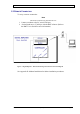
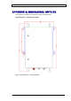
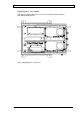
Table Of Contents
- INTRODUCTION
- FUNCTIONAL DESCRIPTION
- DESCRIPTION
- INSTALLATION
- REPEATER MANAGEMENT TOOL (RMT)
- OPERATION
- MAINTENANCE AND TROUBLESHOOTING
- APPENDIX A: MECHANICAL OUTLINE
- APPENDIX B: ALARMS AND LEDS
- APPENDIX C: INSTALLING THE REPEATER IN A LABORATORY SETTING
- APPENDIX D: MODEM INSTALLATION (OPTION)
- APPENDIX E: DEKOLINK WIRELESS LIMITED WARRANTY

DIGITAL REPEATER PRODUCT MANUAL DEKOLINK WIRELESS LTD.
6.2 SMART-ALC FUNCTION
6.2.1 SALC Description
The Smart Automatic Level Control (Smart-ALC) is an innovative solution for
automatic repeater gain adjustment. Combined with advanced control algorithms,
SALC can perform gradual learning of traffic load characteristics and adjust the
Repeater Gain to the desired value.
This automatic operation practically removes the need to make initial settings for
maximal traffic load conditions and eliminates the need for numerous site visits to
take care of Gain adjustment.
SALC also reduces isolation problems and Sync amplification, and maintains
Uplink/Downlink balance.
6.2.2 ALC Function
The Repeater includes the Automatic Level Control (ALC) function on both the
Uplink and Downlink power amplifiers to prevent the saturation of the amplifier.
The amplifier includes a directional coupler and a detector that monitor the output
power. The ALC mechanism samples the output power, and decouples and rectifies
it. The ALC mechanism sends a feedback signal to a voltage variable attenuator
(VVA) that, whenever a high input signal is received, attenuates the signal level so
that the output power of the amplifier does not exceed the preset limit.
This level control ensures that the power amplifier operation stays within the linear
region only, thus preventing saturation and signal distortion.
The ALC protects the amplifiers from overloading and prevents the system from
generating spurious emissions. ALC limits the output power to a constant value
(Maximum output power). The ALC is factory preset to ON state.
6.2.3 RF Gain Setting
The gain range is 59-90 dB. The RF Gain is set separately for Uplink and Downlink.
The gain range should be set via the RMT in accordance with the input signal power
at the Donor antenna, and in accordance with the required Downlink output power.
The gain range is set using the Max Gain function (beware not to exceed isolation
limits, see note below).
The Uplink Gain is set by the Gain Delta field (that is the difference between the
Downlink Gain and the Uplink Gain) in accordance with the system needs. Note that
usually this field is set to “0” for system transparency. Please refer to Installation
Manual.
Note
It is recommended to set the Downlink path gain to a maximum of 18 dB below the
isolation between the Base antenna and the Mobile antenna.
Page 22 Proprietary Data Pub. 302-2004 Rev. 2.0