
User Manual
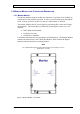
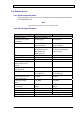
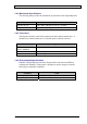
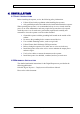
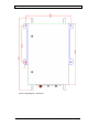
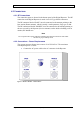
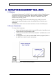
Table Of Contents
- INTRODUCTION
- FUNCTIONAL DESCRIPTION
- DESCRIPTION
- INSTALLATION
- REPEATER MANAGEMENT TOOL (RMT)
- OPERATION
- MAINTENANCE AND TROUBLESHOOTING
- APPENDIX A: MECHANICAL OUTLINE
- APPENDIX B: ALARMS AND LEDS
- APPENDIX C: INSTALLING THE REPEATER IN A LABORATORY SETTING
- APPENDIX D: MODEM INSTALLATION (OPTION)
- APPENDIX E: DEKOLINK WIRELESS LIMITED WARRANTY

DIGITAL REPEATER PRODUCT MANUAL DEKOLINK WIRELESS LTD.
3.4 SPECIFICATIONS
3.4.1 Electrical Specifications
This paragraph provides the electrical, mechanical and environmental specifications
of the Digital Repeater.
Note
Specifications are subject to change without notice.
3.4.2 Electrical Specifications
Parameters Downlink Uplink
Frequency Range Refer to paragraph 1.4..
Pass band Gain @Min
attenuation
90 dB typical 90 dB typical
Filters Bandwidth 12.5 –250 KHz
(Programmable)
12.5 –250 KHz
(Programmable)
Delay 20-80 µsec.
Depending on filter
Bandwidth and
required slope
20-80 µsec. Depends
on filter bandwidth and
required slope.
Channel Ripple ± 0.5 dB max ± 0.5 dB max
Delay Variation ± 300 nSec max ± 300 nSec max
Noise Figure @max gain 6.0 dB 6.0 dB
Gain Control setting (by
RMT software) user
defined
30 dB @1 dB/step 30 dB @1 dB/step
3rd Order Output
Intercept Point
+62 dBm typical +50 dBm typical
IMD @ 4 tone 48 dBc typical
@ 33dbm/tone
48 dBc typical
@ 23 dbm/tone
Power Output @1 dB
Gain Compression
50 Watt 10 Watt
Composite Output
Power
+40 dBm +30 dBm
Automatic Gain Control
(user enable)
15 dB Attenuation
Range
15 dB Attenuation
Range
Impedance Level 50 ohms 50 ohms
V.S.W.R In/Out 1.5: 1 max 1.5: 1 max
Spurious Outputs -13 dBm -20 dBm
Power Supply 90 to 260 VAC, maximum consumig power350W
Page 12 Proprietary Data Pub. 302-2004 Rev. 2.0