
User Manual
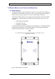
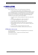
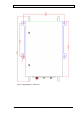
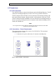
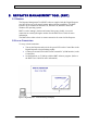
Table Of Contents
- INTRODUCTION
- FUNCTIONAL DESCRIPTION
- DESCRIPTION
- INSTALLATION
- REPEATER MANAGEMENT TOOL (RMT)
- OPERATION
- MAINTENANCE AND TROUBLESHOOTING
- APPENDIX A: MECHANICAL OUTLINE
- APPENDIX B: ALARMS AND LEDS
- APPENDIX C: INSTALLING THE REPEATER IN A LABORATORY SETTING
- APPENDIX D: MODEM INSTALLATION (OPTION)
- APPENDIX E: DEKOLINK WIRELESS LIMITED WARRANTY

DEKOLINK WIRELESS LTD. PRODUCT MANUAL DIGITAL REPEATER
3.3.2 Controller
The integrated Controller Module (Control Box) enables to set all the Digital
Repeater parameters. This module controls the active components in the Repeater as
well as monitors key operating functions. It communicates with two Dekolink Digital
Filter (DDF) modules (Uplink and Downlink) via the serial port communication.
This Module controls the following functions:
RF Gain, •
•
•
•
•
•
Power On/Off,
AGC On/Off
SALC On/Off
Two modes of monitoring and control are available:
External PC - through the serial interface connector in the Control Box.
Remote control - via a modem connected to the Control Box serial interface.
A standard or cellular modem can be installed inside the Repeater enclosure,
refer to Appendix D.
The Controller also sets the Dekolink digital filter parameters for each Dekolink
Digital Filter (DDF) modules (Uplink and Downlink). This Module sets the Center
Frequency, Bandwidth, slopes and Enable/Disable for each of the eight filters. It
allows the independent shaping of the filters by selecting the required filter from a
choice list of frequently used, factory provided filters. The Controller communicates
with the two DDF modules (Uplink and Downlink) via its serial communication port.
Note
If additional unlisted filters are required, please contact
your Dekolink representative.
The Repeater’s parameters, including the filter settings, are defined and downloaded
with the Dekolink’s RMT software. For more information, see the RMT User's
Guide.
This Module also provides Alarm Reports to the Digital Repeater’s outside world.
The Controller transmits in two modes: Polling and Burst. When operating in Burst
Alarm mode, the Controller generates a burst alarm and reports the faults to the local
or remote connection. The Controller software handles the alarm reporting and
parameters transmission to the Repeater’s outside world.
Pub. 302-2004 Rev. 2.0 Proprietary Data Page 11