
User Manual


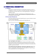
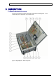

Table Of Contents
- INTRODUCTION
- FUNCTIONAL DESCRIPTION
- DESCRIPTION
- INSTALLATION
- REPEATER MANAGEMENT TOOL (RMT)
- OPERATION
- MAINTENANCE AND TROUBLESHOOTING
- APPENDIX A: MECHANICAL OUTLINE
- APPENDIX B: ALARMS AND LEDS
- APPENDIX C: INSTALLING THE REPEATER IN A LABORATORY SETTING
- APPENDIX D: MODEM INSTALLATION (OPTION)
- APPENDIX E: DEKOLINK WIRELESS LIMITED WARRANTY

DEKOLINK WIRELESS LTD. PRODUCT MANUAL DIGITAL REPEATER
A list of the Digital Repeater main units, in accordance with Figure 2, is provided
below.
1.
2.
3.
4.
5.
6.
7.
8.
9.
10.
11.
12.
13.
14.
15.
16.
17.
18.
Digital Filter Module for the Uplink path (includes status LED)
Uplink Power Amplifier
Duplexer to Base Antenna (low power)
Coupler for Modem Antenna
Isolator for Uplink Amplifier
Channeler (Dual Up/Down Converter for Uplink and Downlink Paths)
Power Supply
Duplexer to Mobile Antenna (high power)
Connections Box (includes Repeater On/Off switch)
Controller Backup Battery Option
Monitor Module (includes alarm LEDs and a LEDs test pushbutton)
Wireless/wireline iDEN Modem Unit – Location
Controller (Control Box - CB) (includes a status LED)
Door Alarm Switch
Door plate
Digital Filter Module for the Downlink path (includes status LED)
External Power indication
Downlink Power Amplifier
Pub. 302-2004 Rev. 2.0 Proprietary Data Page 7