
User Manual


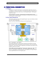
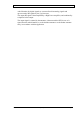

Table Of Contents
- INTRODUCTION
- FUNCTIONAL DESCRIPTION
- DESCRIPTION
- INSTALLATION
- REPEATER MANAGEMENT TOOL (RMT)
- OPERATION
- MAINTENANCE AND TROUBLESHOOTING
- APPENDIX A: MECHANICAL OUTLINE
- APPENDIX B: ALARMS AND LEDS
- APPENDIX C: INSTALLING THE REPEATER IN A LABORATORY SETTING
- APPENDIX D: MODEM INSTALLATION (OPTION)
- APPENDIX E: DEKOLINK WIRELESS LIMITED WARRANTY

DIGITAL REPEATER PRODUCT MANUAL DEKOLINK WIRELESS LTD.
2. FUNCTIONAL DESCRIPTION
2.1 GENERAL
This repeater is designed to help improve communications signal and coverage by
extending the coverage of a base station. The outdoor Donor (Base) antenna receives
the signal from a base station and conveys it to the Digital Repeater. The Repeater
amplifies the signal.
After amplification, the signal is passed through to the Mobile antennas, either
outdoor or indoor. Conversely, signals from handsets are amplified and retransmitted
by the Repeater to the base station.
2.2 FUNCTIONAL DESCRIPTION
The incoming signal processing in the Digital Repeater is processed similarly for both
the Uplink and Downlink paths.
Figure 1 provides a functional block diagram of the Digital Repeater.
Figure 1: Digital Repeater - Block Diagram
The incoming RF signal from either the Base antenna (from the BTS) or from the
Mobile antenna (from the mobile handset) enters the Repeater and is first filtered by
the Duplexer. The incoming signal is amplified by an Automatic Gain Control (AGC)
amplifier, then down-converted.
The input RF signal is then sampled and converted into a digital signal. This digital
signal is filtered using fast parallel logic. The Repeater generates up to eight
separate, programmable, and independent filters using digital processing techniques.
These programmable filters sort the digital signal.
Page 4 Proprietary Data Pub. 302-2004 Rev. 2.0