
User Manual


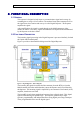
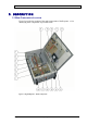

Table Of Contents
- INTRODUCTION
- FUNCTIONAL DESCRIPTION
- DESCRIPTION
- INSTALLATION
- REPEATER MANAGEMENT TOOL (RMT)
- OPERATION
- MAINTENANCE AND TROUBLESHOOTING
- APPENDIX A: MECHANICAL OUTLINE
- APPENDIX B: ALARMS AND LEDS
- APPENDIX C: INSTALLING THE REPEATER IN A LABORATORY SETTING
- APPENDIX D: MODEM INSTALLATION (OPTION)
- APPENDIX E: DEKOLINK WIRELESS LIMITED WARRANTY

DEKOLINK WIRELESS LTD. PRODUCT MANUAL DIGITAL REPEATER
1. INTRODUCTION
1.1 GENERAL
Dekolink’s Digital Repeaters are channel selective amplifiers that amplify signals bi-
directionally between mobile phones and base stations, in cellular and other wireless
mobile telephone systems. Dekolink’s Digital Repeaters employs advanced Digital
Signal Processing (DSP) technology that provides significant advantages over
conventional repeaters.
The Digital Repeaters can be monitored locally or remotely via Dekolink’s Windows-
based Network Management System - RMT software (Refer to the RMT Software
User's Guide for more information).
1.2 APPLICATIONS
Dekolink’s Digital Repeaters introduce new system capabilities that enable a wide
variety of applications particularly when adjacent channel selectivity and/or very high
spectral purity are required. The repeaters provide a solution to situations in which
flexible, high quality and high resolution filtering methods are necessary.
Dekolink’s Digital Repeaters help solve these area coverage problems:
Capacity enhancement for existing coverage, •
•
•
•
•
•
•
•
•
•
•
•
Extended coverage for rural and isolated areas
Improved in-building coverage
Frequency shift (FSR), sometimes defined as frequency translation or
conversion repeater application
Hole filler application whenever there is no coverage of a particular spot in
the cell site (due to terrain topography or urban structures that shadow areas)
Cell extension to improve the coverage of an existing cell
Repeater On Wheels (ROW) application whenever temporary capacity
enhancement is requested, as during a major event when large crowds gather
Repeaters also address special application needs such as traffic balancing.
1.3 FEATURES
Some of the of the Dekolink Digital Repeaters' features are listed below:
50W Downlink (1dB compression point) output power, i.e., 10W Downlink
composite output power
90 dB RF gain
Flexible, software controlled, filter array
One to eight programmable filters
Independent programmable bandwidth for each filter
(12.5 to 250 KHz)
Pub. 302-2004 Rev. 2.0 Proprietary Data Page 1