
Installation and Operating Instructions
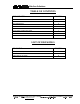
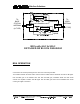
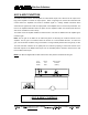
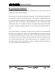
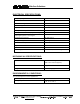
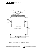
Table Of Contents
- AND
- MW-CBDA-TDMAB-1W60-A
- CELLULAR
- BI-DIRECTIONAL AMPLIFIER
- BDA with AGC & MGC
- DETAILED RF BLOCK DIAGRAM
- _
- The switch on the RF amplifier enables the AGC function. If the AGC is disabled then the amplifier gives maximum gain.
- MGC: The RF gain of the BDA can be reduced by about 15 dB using the continuos trimmer on the amplifier. The RF gain is at maximum when the trimmer is at anti-clockwise direction. To reduce the gain, turn the trimmer clockwise using a screwdriver. Turning
- The AGC and MGC functions for the uplink path are reached by opening a small cover located on the DBA side adjacent to the Mobile antenna port. For the downlink path the window is located on the side near the Base antenna port.
- Note: The BDA is shipped with the AGC switch in the OFF position and maximum RF gain.

Wireless Solutions
48 Mivtza Kadesh St. Bene Beraq 51203 , ISRAEL Tel: +972-3-6175639 Fax:+972-3-6175962
3 RI HPDLO
trm1@elisra.com
:HE VLWH ZZZPZHOLVUDFRP 5HY%
ELECTRICAL SPECIFICATIONS:
Frequency Range Up Link : 835 849 MHz
Down Link : 880 894 MHz
Passband Gain @ min attenuation 60 dB minimum
Passband Ripple 1.5 dB typical
Output Power AGC Set +24 1 dBm
AGC Dynamic Range 30 dB min
MGC (Manual Gain Control) Dynamic Range 15 dB min
Noise Figure @+25 C at max gain
6.0 dB max
3rd Order Intercept point +45 dBm typical
IMD @2 tone @+20 dBm/carrier 50 dBc typical
Isolation between Up/Down Link 75 dB min
Impedance Level 50 Ohms
VSWR 1.5 : 1 max
Power Supply 80 to 240 VAC; 50 to 60 Hz; @500 mA
MECHANICAL SPECIFICATIONS:
Size : 10 x 10 x 5 inch approx.
(250 x 250 x 120 mm approx.)
RF Connectors : N-type Female
Weight
: 15 Lbs. (7 kg.) approx.
ENVIRONMENTAL CONDITIONS:
The unit is designed for indoor applications:
Operating temperature
: - 30 C to + 50 C
Storage temperature
: - 50 C to + 80 C