
Installation and Operating Instructions
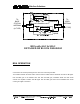
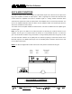
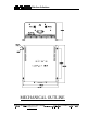
Table Of Contents
- AND
- MW-CBDA-TDMAB-1W60-A
- CELLULAR
- BI-DIRECTIONAL AMPLIFIER
- BDA with AGC & MGC
- DETAILED RF BLOCK DIAGRAM
- _
- The switch on the RF amplifier enables the AGC function. If the AGC is disabled then the amplifier gives maximum gain.
- MGC: The RF gain of the BDA can be reduced by about 15 dB using the continuos trimmer on the amplifier. The RF gain is at maximum when the trimmer is at anti-clockwise direction. To reduce the gain, turn the trimmer clockwise using a screwdriver. Turning
- The AGC and MGC functions for the uplink path are reached by opening a small cover located on the DBA side adjacent to the Mobile antenna port. For the downlink path the window is located on the side near the Base antenna port.
- Note: The BDA is shipped with the AGC switch in the OFF position and maximum RF gain.

Wireless Solutions
48 Mivtza Kadesh St. Bene Beraq 51203 , ISRAEL Tel: +972-3-6175639 Fax:+972-3-6175962
3 RI HPDLO
trm1@elisra.com
:HE VLWH ZZZPZHOLVUDFRP 5HY%
BDA with AGC & MGC
DETAILED RF BLOCK DIAGRAM
BDA OPERATION
connected to the antenna pointing into the area to be covered by the BDA.
The isolation between the base station antenna and the mobile antenna should be at least 12 dB higher
than the BDA gain. If the isolation were less than the BDA gain, oscillation would start and would
saturate the amplifier. Isolation few dB higher than the BDA gain cannot start oscillations but would
causes gain ripple in the band.
'XSOH[HU
'RZQOLQN
'XSOH[HU
8SOLQN
72
%$6(
67$7,21
$17(11$
72
$5($
$17(11$
17<3(
17<3(
$*& 5) $03/,),(5
$*& &,5&8,7
'(7(&7(5
$*& &,5&8,7
'(7(&7(5
$*& 5) $03/,),(5
&283/(5
&283/(5
0*&
0*&