
Installation Instructions
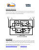
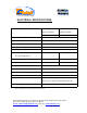
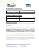
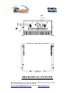
Table Of Contents
- AND
- BOOSTER
- The switch on the RF amplifier enables the AGC function. If the AGC is disabled then the amplifier gives maximum gain.
- The AGC ON/OFF and GAIN SETTING functions for the up link path are reached by opening the small slide door located on the Booster left side, adjacent to the BASE antenna port. For the down link path the door is on the right side adjacent to the MOBILE an
- Limited Warranty

Dekolink Wireless Ltd., 16 Bazel St., Qiryat-Arieh Petah-Tikva Israel, 49510
Tel: 972-3-9180-180; Fax: 972-3- 190-9180
Email: marketing@dekolink.com
BOOSTER OPERATION
The RF connection is made via two type “N” female connectors. The RF connector labeled “Base” is
connected to the base station. The RF connection labeled “Mobile” is connected to the antenna of
area to be covered by the Booster; such as inside the building.
Duplexer
Downlink
Duplexer
Uplink
LNA
Attenuator
Power
Monitor
PA
AGC
Attenuator
Power
Monitor
PA
AGC
IBDB-10W40
RF BLOCK DIAGRAM
TO
BASE
TO
MOBILE
AGC FUNCTION
The Booster has AGC function on both paths that serve to prevent the saturation of the power
amplifier. Their amplifier has a directional coupler and a detector at the output of the high power
amplifier to monitor the output power. When a high signal is received the automatic level control
; Web site: www.dekolink.com
Rev 0 02/03 Page 4 of 9