
Installation Instructions
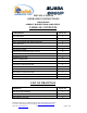
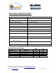
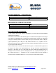
Table Of Contents

Dekolink Wireless Ltd.;16 Bazel St.Qiryat-Arieh Petah-Tikva Israel, 49510
Tel- 972-3-9180-180; Fax-972-3- 190-9180 ;
Email-marketing@dekolink.com
:ELECTRICAL SPECIFICATIONS
Frequency Range (MHz) SEE TABLE
Passband Gain @Min attenuation 80 dB nominal
Passband Ripple
± 1.5 dB typical
Manual Attenuation Range 0 to 30 dB in 2 dB step
Noise Figure 6.0 dB max
Impedance level 50 ohms
V.S.W.R In/Out 1.5 : 1 max
AGC Selection By ON/OFF Switch
AGC Attenuation Range 25 dB typical
AGC LED Indication LED turn ON when power reaches AGC Set
Power Level. (both at On and Off positions).
AGC Factory Power Preset +24 dBm nom.
Amplifier Power Output
@1 dB Compression
1 Watts
3rd Order output Intercept point +45 dBm typical
Power Supply 110/220V AC, 50-60 Hz /1A
System Frequency Range
SYSTEM TYPE
MODEL No
DOWN-
LINK
UP-
LINK
E-SMR (iDEN) MW-CBDA-ESMR-1W80A 851-866 806-821
SMR 800-Public Safety MW-CBDA-SMR-1W80A-PS8 851-869 806-824
SMR - 900 MHz MW-CBDA-SMR-1W80A-PS9 935-941 892-902
GSM MW-CBDA-GSM-1W80A 935-960 890-915
TDMA Band B MW-CBDA-CELLB-1W80A 880-894 835-849
CDMA/TDMA/N-AMPS MW-CBDA-AB-1W80A 870-894 825-849
;
Web site- www.dekolink.com rev 5 11/02 page 9 of 12