
Installation Instructions
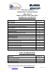
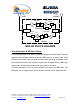
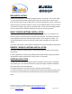
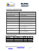
Table Of Contents

Dekolink Wireless Ltd.;16 Bazel St.Qiryat-Arieh Petah-Tikva Israel, 49510
Tel- 972-3-9180-180; Fax-972-3- 190-9180 ;
Email-marketing@dekolink.com
DIAGNOSTICS GUIDE
The BDA provides long term, carefree operation and requires no periodic maintenance.
This section covers possible problems related to the installation environment.
RF Faults and RF Power Amplifiers LED Indications:
The LEDs on the power amplifier are set to turn on when the transmitted power has
reached or exceeded the specified composite power.
Normally the LED at the downlink power amplifier should be on indicating good forward
power transmission. The LED on the uplink power amplifier turns on only when a near
by mobile is transmitting.
Indication Cause Action
Downlink LED does
not light
Indicates low RF power at
downlink path
Check base antenna connection
Check antenna alignment to base.
Increase BDA RFgain.
Downlink LED lights
(This is not a fault)
Indicates good power
transmission in the downlink
amplifier.
Make sure the amplifier is
not overloaded
Turn AGC on, or reduce gain so that LED
just turns from off to on.
Set the same gain for the uplink channel
Uplink LED lights all
the time
Bad antenna isolation
causing the repeater system
to oscillate
Improve the isolation between the
antennas or reduce RF gain. To verify
disconnect one RF port; LED should turn
off
Uplink LED lights all
the time
Faulty system. Can be
diplexer or power amplifier
fault
System fault. To verify disconnect one RF
port to verify. If LED remains on then
system is faulty.
Excessive
intermodulation or
spurious
Amplifier oscillation caused
by insufficient isolation
Improve the isolation between the
antennas or reduce RF gain.
Excessive noise in
downlink
High input power causing
amplifier overload
Turn AGC on, or reduce gain so that LED
just turns from off to on. Set the same
gain for the uplink channel
;
Web site- www.dekolink.com rev 5 11/02 page 8 of 12