
User's Manual
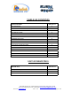
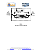
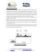
Table Of Contents
- BDA
- RF BLOCK DIAGRAM
- The switch on the RF amplifier enables the AGC function. If the AGC is disabled then the amplifier gives maximum gain.
- MGC: The RF gain of the BDA can be reduced by about 15 dB using the continuos trimmer on the amplifier. The RF gain is at maximum when the trimmer is at counter-clockwise direction. To reduce the gain, turn the trimmer clockwise using a screwdriver. Turn
- The AGC and MGC functions for the uplink path are reached by opening a small cover located on the DBA side adjacent to the Mobile antenna port. For the downlink path the window is located on the side near the Base antenna port.
- Limited Warranty
INSTALLATION STEPS
1. Install all antennas and connect them to the BDA inputs.
2. Open the access windows at the sides of the BDA so that the variable attenuator is reached and the
LED is visible.
3. Turn the AGC On. This AGC limits the output power of the BDA. The AGC on the Downlink path
guarantees constant downlink power when and if the Donor power changes.
4. Set downlink gain to minimum; uplink gain to minimum ( by turning the gain control trimmer
clockwise).
5. Increase the downlink channel gain (by turning the gain control trimmer counterclockwise) till the
LED turns from off to on. This is the best gain setting giving highest usable power.
6. The LED on the downlink power amplifier will illuminate if adequate donor power has reached the
BDA. If the donor power is low the LED will not lit and the BDA usable power is not used efficiently.
7. Set the uplink gain to the same as the downlink gain.
8. Check that the uplink LED on the BDA monitor does not lit permanently. This LED would lit
permanently If the isolation between antennas is low (BDA oscillations) or the BDA is faulty.
9. If the uplink LED light permanently then:
• Disconnect one of the cables from the BDA connectors and connect a load at the
connectors.
• If the LED on this amplifier illuminates permanently then the BDA is faulty (oscillating) and
needs replacing.
• If the LEDs stops illuminating then the isolation between the donor and remote antennas is
low. Either improve the isolation (e.g. increase separation) or reduce BDA gain.
• To reduce gain, reconnect the antenna cables. Reduce the gain at both uplink and downlink
path until this LED stops illuminating. Reduce the gain further by 10 dB. This is the
maximum usable gain.
Dekolink Wireless Ltd.;16 Bazel St.Qiryat-Arieh Petah-Tikva Israel, 49510
Tel- 972-3-9180-180; Fax-972-3- 190-9180 ; Email-marketing@dekolink.com
;
Web site-
www.dekolink.com
r
ev 8
10/03
page 7 of 12