
User's Manual
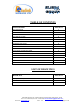
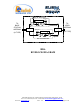
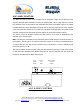
Table Of Contents
- BDA
- RF BLOCK DIAGRAM
- The switch on the RF amplifier enables the AGC function. If the AGC is disabled then the amplifier gives maximum gain.
- MGC: The RF gain of the BDA can be reduced by about 15 dB using the continuos trimmer on the amplifier. The RF gain is at maximum when the trimmer is at counter-clockwise direction. To reduce the gain, turn the trimmer clockwise using a screwdriver. Turn
- The AGC and MGC functions for the uplink path are reached by opening a small cover located on the DBA side adjacent to the Mobile antenna port. For the downlink path the window is located on the side near the Base antenna port.
- Limited Warranty
BDA INSTALLATION
Install the BDA Repeater in a shielded, ventilated and easy to reach area. Use low loss cables to
connect antennas to the BDA. Install the BDA close to the service area to improve output power and
noise figure. Mount the BDA with RF connecters pointing down. The RF connection is made via two
type “N” female connectors. The RF connector labeled “Base” must be connected to the antenna;
usually a Yagi; pointing to the base station. The RF connection labeled “Mobile” must be connected to
the antenna pointing into the area to be covered by the BDA.
BASE / DONOR ANTENNA INSTALLATION
Typically this is a directional antenna such as Yagi or Dish antenna of 10 to 15 dB gain. This antenna is
pointed to the base station to get maximum input power. This antenna should be in line of sight with the
base site. Raise this antenna higher if no line of sight is achieved. The required Base signals should be
the dominant signals; at least 6 dB higher power than other signals.
Choose the antenna site to get the maximum isolation from the remote (mobile serving) antenna.
REMOTE / SERVICE ANTENNA INSTALLATION
The remote antenna is an Omni antenna or a directional antenna according to the coverage
requirements.
For indoor applications covering a large building, the RF signals are split using power dividers and
distributed to many antennas each covering a floor or a small area.
ANTENNA ISOLATION
For proper operation the isolation between these two antennas must be at least 12 dB higher than the
BDA gain. Lower isolation would lead to high in-band ripple. Oscillations will build up when the isolation
is lower than BDA gain.
The isolation between the antennas is critical for high gain outdoor repeaters.
To measure the isolation; inject a known signal into one antenna and measure the power at the other
antenna. This should be done across the frequency range of both uplink and downlink bands.
Dekolink Wireless Ltd.;16 Bazel St.Qiryat-Arieh Petah-Tikva Israel, 49510
Tel- 972-3-9180-180; Fax-972-3- 190-9180 ; Email-marketing@dekolink.com
;
Web site-
www.dekolink.com
r
ev 8
10/03
page 6 of 12