
User's Manual
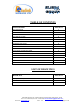
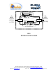
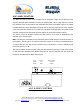
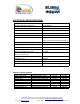
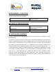
Table Of Contents
- BDA
- RF BLOCK DIAGRAM
- The switch on the RF amplifier enables the AGC function. If the AGC is disabled then the amplifier gives maximum gain.
- MGC: The RF gain of the BDA can be reduced by about 15 dB using the continuos trimmer on the amplifier. The RF gain is at maximum when the trimmer is at counter-clockwise direction. To reduce the gain, turn the trimmer clockwise using a screwdriver. Turn
- The AGC and MGC functions for the uplink path are reached by opening a small cover located on the DBA side adjacent to the Mobile antenna port. For the downlink path the window is located on the side near the Base antenna port.
- Limited Warranty

BDA OVERVIEW:
The Bi-Directional Amplifier (BDA) assembly provides an exceptional repeater/booster
performances to extend the coverage area of radio communications in buildings and RF
shielded environments.
Features such as high linearity power amplifiers are contributing for the overall improved
system linearity performances. The unit is based on a duplexed path configuration, having
sharp out of band attenuation for improved isolation between the receiving and transmitting
paths.
BLOCK DIAGRAM DESCRIPTION:
The CBDA Downlink path receives the RF signals from base station amplifies them and
transmits them to the subscriber. The BDA Uplink path receives the RF signals from the
subscriber amplifies them and transmits them to the base station. Two duplexers frequency
separate the signals to the proper amplifying path and isolate the two signals.
The amplifiers in this BDA have an AGC option switch. When switched on, the AGC circuit
limits the amplifier output power. The AGC circuit senses the output power and introduces
more attenuation, when the output power exceeds the preset level of +27dBm*. This way the
gain of the amplifier is reduced, its output power is limited and the intermodulations products
are kept below the desired level.
In this manner the output power cannot exceed the +27 dBm* preset power and the IMD levels
are always kept below –13 dBm.
The AGC amplifier has a Power LED lamp that illuminates when the output power has reached
the preset power limit.
*Note
: AGC preset level can be factory set to +24dBm upon customer request.
In addition the BDA has a trimmer that enables the reduction of the gain by 15 dB.
Dekolink Wireless Ltd.;16 Bazel St.Qiryat-Arieh Petah-Tikva Israel, 49510
Tel- 972-3-9180-180; Fax-972-3- 190-9180 ; Email-marketing@dekolink.com
;
Web site-
www.dekolink.com
r
ev 8
10/03
page 3 of 12