INSTALLATION AND OPERATING INSTRUCTIONS FOR MW-CBDA SERIES 1W60A COMPACT BI-DIRECTIONAL AMPLIFIERS Dekolink Wireless Proprietary and Confidential Information. Copying, Distribution, and Disclosure are irelessExpress Ltd.;16 Authorization Bazel St.Qiryat-Arieh Petah-Tikva Israel, 49510 . pDekolink rohibited W without from Dekolink Wireless Company Tel- 972-3-9180-180; Fax-972-39180 190 ; Email-marketing@dekolink.com; This document is protected by all applicable copyright laws.
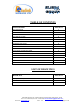
TABLE OF CONTENTS PARAGRAPH PAGE No BDA OVERVIEW 3 BLOCK DAIGRAM DESCRIPTION 3 AGC & MGC FUNCTION 5 BDA INSTALLATION 6 BASE/DONOR ANTENNA INSTALLATION 6 REMOTE/SERVICE ANTENNA INSTALLATION 6 ANTENNA ISOLATION 6 INSTALLATION STEPS 7 DIAGNOSTICS GUIDE 8 ELECTRICAL SPECIFICATIONS 9 SYSTEM FREQUENCY RANGE 9 ENVIRONMENTAL CONDITIONS 10 MECHANICAL SPECIFICATIONS 10 RF EXPOSURE WARNING 10 DEKOLINK WIRELESS LIMITED WARRANTY 12 LIST OF DRAWINGS DRAWING PAGE No BDA (WITH AGC) RF BLOC
BDA OVERVIEW: The Bi-Directional Amplifier (BDA) assembly provides an exceptional repeater/booster performances to extend the coverage area of radio communications in buildings and RF shielded environments. Features such as high linearity power amplifiers are contributing for the overall improved system linearity performances. The unit is based on a duplexed path configuration, having sharp out of band attenuation for improved isolation between the receiving and transmitting paths.
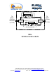
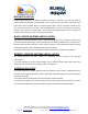
MGC AGC RF AMPLIFIER DETECTER AGC CIRCUIT TO BASE STATION ANTENNA COUPLER Duplexer Downlink Duplexer DETECTER (N-TYPE) AGC CIRCUIT (N-TYPE) TO AREA ANTENNA MGC COUPLER Uplink AGC RF AMPLIFIER BDA RF BLOCK DIAGRAM Dekolink Wireless Ltd.;16 Bazel St.Qiryat-Arieh Petah-Tikva Israel, 49510 Tel- 972-3-9180-180; Fax-972-3-9180-190; Email-marketing@dekolink.com; rev 8 10/03 page 4 of 12 Web site- www.dekolink.
AGC & MGC FUNCTION The BDA has AGC function. Their amplifier has a directional coupler and a detector at the output of the high power amplifier to monitor the output power. When a high signal is received the automatic level control detects the amplitude and sends a feedback signal to a voltage variable attenuator which attenuates the signal level so that the output power of the amplifier does not exceed the preset limit.
BDA INSTALLATION Install the BDA Repeater in a shielded, ventilated and easy to reach area. Use low loss cables to connect antennas to the BDA. Install the BDA close to the service area to improve output power and noise figure. Mount the BDA with RF connecters pointing down. The RF connection is made via two type “N” female connectors. The RF connector labeled “Base” must be connected to the antenna; usually a Yagi; pointing to the base station.
INSTALLATION STEPS 1. Install all antennas and connect them to the BDA inputs. 2. Open the access windows at the sides of the BDA so that the variable attenuator is reached and the LED is visible. 3. Turn the AGC On. This AGC limits the output power of the BDA. The AGC on the Downlink path guarantees constant downlink power when and if the Donor power changes. 4. Set downlink gain to minimum; uplink gain to minimum ( by turning the gain control trimmer clockwise). 5.
DIAGNOSTICS GUIDE The BDA provides long term, carefree operation and requires no periodic maintenance. This section covers possible problems related to the installation environment. RF Faults and RF Power Amplifiers LED Indications The LEDs on the power amplifier are set to turn on when the transmitted power has reached or exceeded the specified composite power. Normally the LED at the downlink power amplifier should be on indicating good forward power transmission.
ELECTRICAL SPECIFICATIONS: Frequency Range SEE TABLE Passband Gain @ min attenuation 60 dB minimum Passband Ripple ±1.5 dB typical Output Power AGC Set * +27 dBm nom. AGC Selection By ON/OFF Switch AGC Dynamic Range 30 dB min AGC LED Indication LED turn ON when power reaches AGC Set Power Level. (both at On and Off positions). MGC (Manual Gain Control) Dynamic Range 15 dB min Noise Figure @+25°C and max gain 5.
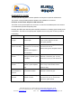
ENVIRONMENTAL CONDITIONS: The unit is designed for indoor applications: Operating temperature - 30°C to + 50°C Storage temperature - 50°C to + 80°C MECHANICAL SPECIFICATIONS: Size 10 x 10 x 5 inch approx. (250 x 250 x 120 mm approx.) RF Connectors N-type Female Weight 15 Lbs. (7 kg.) approx.
MECHANICAL OUTLINE Dekolink Wireless Ltd.;16 Bazel St.Qiryat-Arieh Petah-Tikva Israel, 49510 Tel- 972-3-9180-180; Fax-972-3-9180-190; Email-marketing@dekolink.com; rev 8 10/03 page 11 of 12 Web site- www.dekolink.
DEKOLINK WIRELESS LIMITED WARRANTY Dekolink Wireless [Ltd.] (“Dekolink”), manufacturer of this product (the “Product”) warrants to the original purchaser (“Purchaser”) that the Product is free from defects in materials and workmanship for a term that ends on the earlier of twelve (12) months from the date of activation of the Product or fifteen (15) months from the date of shipment of the Product by Dekolink.