
User Manual
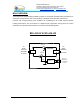
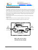
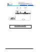
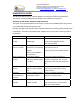
Table Of Contents
- AND
- MW-CBDA-800A-1W60-PG2
- CELLULAR BI-DIRECTIONAL AMPLIFIERS
- BDA with AGC & MGC
- RF BLOCK DIAGRAM
- _
- The switch on the RF amplifier enables the AGC function. If the AGC is disabled then the amplifier gives maximum gain.
- MGC: The RF gain of the BDA can be reduced linearly by about 15 dB using the trimmer on the amplifier. The RF gain is at maximum when the trimmer is at anti-clockwise direction. To reduce the gain, turn the trimmer clockwise using a screwdriver. Turning
- The AGC and MGC functions for the uplink path are reached by opening a small cover located on the DBA side adjacent to the Mobile antenna port. For the downlink path the window is located on the side near the Base antenna port.
- Note: The BDA is shipped with the AGC switch in the OFF position and maximum RF gain.
- Limited Warranty

Dekolink WIRELESS Ltd.
16 Bazel St. Qiryat-Arieh Petah-Tikva, Israel, 49510
Tel- 972-3-9180-180 Fax-972-3- 190-9180
e-mail: marketing@dekolink.com
web www.dekolink.com
BDA OPERATION
The BDA comes with a standard 3-wire male plug with phase, neutral and safety ground wires. A high
efficiency DC switching power supply supplies DC power to two amplifiers (Uplink and Downlink) and
the Power On lamp.
The RF connection is made via two type “N” female connectors. The RF connector labeled “Base” must
be connected to the antenna pointing to the base station. The RF connection labeled “Mobile” must be
connected to the antenna pointing into the area to be covered by the BDA.
The isolation between the base station antenna and the mobile antenna should be at least 12 dB higher
than the BDA gain. If the isolation is less than the BDA gain, oscillation would start and would saturate
the amplifier. Isolation of few dB higher than the BDA gain cannot start oscillations but would causes
gain ripple in the band.
AGC & MGC FUNCTION
The BDA model No: MW-CBDA-800A-1W60-PG2 has AGC function. Their amplifier has a directional
coupler and a detector at the output of the high power amplifier to monitor the output power. When a
high signal is received the automatic level control detects the amplitude and sends a feedback signal to
a voltage variable attenuator, which attenuates the signal level so that the output power of the amplifier
does not exceed the preset limit. The LED on the amplifier illuminates when the power out the amplifier
is within the set limit (both when the AGC is On and when the AGC is OFF).
The switch on the RF amplifier enables the AGC function. If the AGC is disabled then the amplifier gives
maximum gain.
MGC: The RF gain of the BDA can be reduced linearly by about 15 dB using the trimmer on the
amplifier. The RF gain is at maximum when the trimmer is at anti-clockwise direction. To reduce the
gain, turn the trimmer clockwise using a screwdriver. Turning it halfway would reduce the gain by 7.5
dB.
The AGC and MGC functions for the uplink path are reached by opening a small cover located on the
DBA side adjacent to the Mobile antenna port. For the downlink path the window is located on the side
near the Base antenna port.
Note:
The BDA is shipped with the AGC switch in the OFF position and maximum RF gain.
Page 5 of 13 CBDA-800A-1W60-PG2 INST2.doc REV. 0 09.03