
User Manual
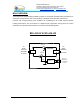
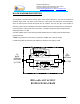
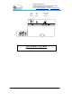
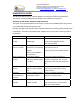
Table Of Contents
- AND
- MW-CBDA-800A-1W60-PG2
- CELLULAR BI-DIRECTIONAL AMPLIFIERS
- BDA with AGC & MGC
- RF BLOCK DIAGRAM
- _
- The switch on the RF amplifier enables the AGC function. If the AGC is disabled then the amplifier gives maximum gain.
- MGC: The RF gain of the BDA can be reduced linearly by about 15 dB using the trimmer on the amplifier. The RF gain is at maximum when the trimmer is at anti-clockwise direction. To reduce the gain, turn the trimmer clockwise using a screwdriver. Turning
- The AGC and MGC functions for the uplink path are reached by opening a small cover located on the DBA side adjacent to the Mobile antenna port. For the downlink path the window is located on the side near the Base antenna port.
- Note: The BDA is shipped with the AGC switch in the OFF position and maximum RF gain.
- Limited Warranty

Dekolink WIRELESS Ltd.
16 Bazel St. Qiryat-Arieh Petah-Tikva, Israel, 49510
Tel- 972-3-9180-180 Fax-972-3- 190-9180
e-mail: marketing@dekolink.com
web www.dekolink.com
BLOCK DIAGRAM DESCRIPTION:
The amplifiers in this BDA have an AGC option switch. When switched on, the AGC circuit limits the
amplifier output power. The AGC circuit senses the output power and introduces more attenuation,
when the output power exceeds the preset level of +27dBm*. This way the gain of the amplifier is
reduced, its output power is limited and the intermodulations products are kept below the desired level.
In this manner the output power cannot exceed the +27 dBm* preset power and the IMD levels are
always kept below –13 dBm.
The AGC amplifier has a Power LED lamp that illuminates when the output power has reached the
preset power limit.
*note
: AGC preset level can be factory modified to +24dBm upon customer request.
In addition the BDA has a trimmer that enables the reduction of the gain by 15 dB.
Duplexer
Downlink
Duplexer
Uplink
TO
BASE
STATION
ANTENNA
TO
AREA
ANTENNA
(N-TYPE)
(N-TYPE)
AGC RF AMPLIFIER
AGC CIRCUIT
DETECTER
AGC CIRCUIT
DETECTER
AGC RF AMPLIFIER
COUPLER
COUPLER
MGC
MGC
BDA with AGC & MGC
RF BLOCK DIAGRAM
Page 4 of 13 CBDA-800A-1W60-PG2 INST2.doc REV. 0 09.03