
User Manual
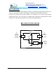
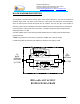
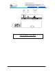
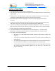
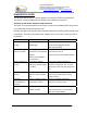
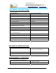
Table Of Contents
- AND
- MW-CBDA-800A-1W60-PG2
- CELLULAR BI-DIRECTIONAL AMPLIFIERS
- BDA with AGC & MGC
- RF BLOCK DIAGRAM
- _
- The switch on the RF amplifier enables the AGC function. If the AGC is disabled then the amplifier gives maximum gain.
- MGC: The RF gain of the BDA can be reduced linearly by about 15 dB using the trimmer on the amplifier. The RF gain is at maximum when the trimmer is at anti-clockwise direction. To reduce the gain, turn the trimmer clockwise using a screwdriver. Turning
- The AGC and MGC functions for the uplink path are reached by opening a small cover located on the DBA side adjacent to the Mobile antenna port. For the downlink path the window is located on the side near the Base antenna port.
- Note: The BDA is shipped with the AGC switch in the OFF position and maximum RF gain.
- Limited Warranty

Dekolink WIRELESS Ltd.
16 Bazel St. Qiryat-Arieh Petah-Tikva, Israel, 49510
Tel- 972-3-9180-180 Fax-972-3- 190-9180
e-mail: marketing@dekolink.com
web www.dekolink.com
BDA OVERVIEW:
The Bi-Directional Amplifier (BDA) assembly provides an exceptional repeater/booster performances to
extend the coverage area of radio communications in buildings and RF shielded environments.
Features such as high linearity power amplifiers are contributing for the overall improved system
linearity performances. The unit is based on a duplexed path configuration, having sharp out of band
attenuation for improved isolation between the receiving and transmitting paths.
BDA BLOCK DIAGRAM
Duplexer
RF
AMPLIFIER
Downlink
Duplexer
Uplink
RF
AMPLIFIER
TO
BASE
STATION
ANTENNA
TO
AREA
ANTENNA
POWER
SUPPLY
(N-TYPE)
(N-TYPE)
(STANDARD
3 WIRE)
INPUT AC
CONNECTOR
DC
Page 3 of 13 CBDA-800A-1W60-PG2 INST2.doc REV. 0 09.03