
Installation and Operating Instructions
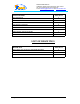
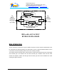
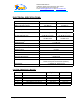
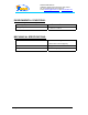
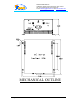
Table Of Contents
- AND
- MW-CBDA-PCS-X-1W65-A
- CELLULAR
- BI-DIRECTIONAL AMPLIFIER
- BDA with AGC & MGC
- RF BLOCK DIAGRAM
- _
- The switch on the RF amplifier enables the AGC function. If the AGC is disabled then the amplifier gives maximum gain.
- MGC: The RF gain of the BDA can be reduced by about 15 dB using the continuos trimmer on the amplifier. The RF gain is at maximum when the trimmer is at anti-clockwise direction. To reduce the gain, turn the trimmer clockwise using a screwdriver. Turning
- The AGC and MGC functions for the uplink path are reached by opening a small cover located on the DBA side adjacent to the Mobile antenna port. For the downlink path the window is located on the side near the Base antenna port.
- Note: The BDA is shipped with the AGC switch in the OFF position and maximum RF gain.

Dekolink WIRELESS Ltd.
16 Bazel St. Qiryat-Arieh Petah-Tikva, Israel, 49510
Tel- 972-3-9180-180 Fax-972-3- 190-9180
e-mail: marketing@decolink.com
web www.decolink.com
ENVIRONMENTAL CONDITIONS:
The unit is designed for indoor applications:
Operating temperature
: - 30
°
C to + 50
°
C
Storage temperature
: - 50
°
C to + 80
°
C
MECHANICAL SPECIFICATIONS:
Size : 10 x 10 x 5 inch approx.
(250 x 250 x 120 mm approx.)
RF Connectors : N-type Female
Weight
: 15 Lbs. (7 kg.) approx.
Page 8 of 9 CBDA PCSX 1W65 Install.doc