
Installation and Operating Instructions
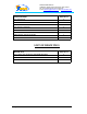
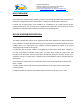
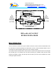
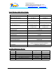
Table Of Contents
- AND
- MW-CBDA-PCS-X-1W65-A
- CELLULAR
- BI-DIRECTIONAL AMPLIFIER
- BDA with AGC & MGC
- RF BLOCK DIAGRAM
- _
- The switch on the RF amplifier enables the AGC function. If the AGC is disabled then the amplifier gives maximum gain.
- MGC: The RF gain of the BDA can be reduced by about 15 dB using the continuos trimmer on the amplifier. The RF gain is at maximum when the trimmer is at anti-clockwise direction. To reduce the gain, turn the trimmer clockwise using a screwdriver. Turning
- The AGC and MGC functions for the uplink path are reached by opening a small cover located on the DBA side adjacent to the Mobile antenna port. For the downlink path the window is located on the side near the Base antenna port.
- Note: The BDA is shipped with the AGC switch in the OFF position and maximum RF gain.

Dekolink WIRELESS Ltd.
16 Bazel St. Qiryat-Arieh Petah-Tikva, Israel, 49510
Tel- 972-3-9180-180 Fax-972-3- 190-9180
e-mail: marketing@decolink.com
web www.decolink.com
ELECTRICAL SPECIFICATIONS:
Uplink Downlink
Frequency Range (MHz) See Table See Table
CDMA Total Output Power +24 dBm typ
+27 dBm typ
AGC Factory Power Preset
+24± 1dBm
+27±1 dBm
3rd Order Output Intercept point
+45 dBm typical +48 dBm typical
3rd Order IMD (dBc typ)
50 dBc @ two tones
+20 dBm each
50 dBc @ two tones
+23 dBm each
Passband Gain @Min attenuation 65 dB min
Passband Ripple
± 1.5 dB max
Manual Attenuation Range (Continuous) 15 dB min
Noise Figure 5.0 dB max
Impedance level 50 ohms
V.S.W.R In/Out 1.8 : 1 max
AGC Selection By ON/OFF Switch
AGC Attenuation Range 30 dB typical
AGC LED Indication LED turn ON when power reaches AGC Set
Power Level. (both at On and Off positions).
Power Supply : 110/220V AC, 50-60 Hz /1A
SYSTEM FREQUENCY RANGE:
BLOCK Model No. Up Link Down Link
A MW-CBDA-PCS-A-1W65-A 1850-1865 1930-1945
B MW-CBDA-PCS-B-1W65-A 1870-1885 1950-1965
C MW-CBDA-PCS-C-1W65-A 1895-1910 1975-1990
D MW-CBDA-PCS-D-1W65-A 1865-1870 1945-1950
E MW-CBDA-PCS-E-1W65-A 1885-1890 1965-1970
F MW-CBDA-PCS-F-1W65-A 1890-1895 1970-1975
Page 7 of 9 CBDA PCSX 1W65 Install.doc