
Installation and Operating Instructions
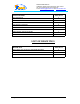
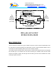
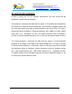
Table Of Contents
- AND
- MW-CBDA-PCS-X-1W65-A
- CELLULAR
- BI-DIRECTIONAL AMPLIFIER
- BDA with AGC & MGC
- RF BLOCK DIAGRAM
- _
- The switch on the RF amplifier enables the AGC function. If the AGC is disabled then the amplifier gives maximum gain.
- MGC: The RF gain of the BDA can be reduced by about 15 dB using the continuos trimmer on the amplifier. The RF gain is at maximum when the trimmer is at anti-clockwise direction. To reduce the gain, turn the trimmer clockwise using a screwdriver. Turning
- The AGC and MGC functions for the uplink path are reached by opening a small cover located on the DBA side adjacent to the Mobile antenna port. For the downlink path the window is located on the side near the Base antenna port.
- Note: The BDA is shipped with the AGC switch in the OFF position and maximum RF gain.

Dekolink WIRELESS Ltd.
16 Bazel St. Qiryat-Arieh Petah-Tikva, Israel, 49510
Tel- 972-3-9180-180 Fax-972-3- 190-9180
e-mail: marketing@decolink.com
web www.decolink.com
Duplexer
Downlink
Duplexer
Uplink
TO
BASE
STATION
ANTENNA
TO
AREA
ANTENNA
(N-TYPE)
(N-TYPE)
AGC RF AMPLIFIER
AGC CIRCUIT
DETECTER
AGC CIRCUIT
DETECTER
AGC RF AMPLIFIER
COUPLER
COUPLER
MGC
MGC
BDA with AGC & MGC
RF BLOCK DIAGRAM
BDA OPERATION
The RF connection is made via two type “N” female connectors. The RF connector labeled “Base” must
be connected to the antenna pointing to the base station. The RF connection labeled “Mobile” must be
connected to the antenna pointing into the area to be covered by the BDA.
The isolation between the base station antenna and the mobile antenna should be at least 12 dB higher
than the BDA gain. If the isolation were less than the BDA gain, oscillation would start and would
saturate the amplifier. Isolation few dB higher than the BDA gain cannot start oscillations but would
causes gain ripple in the band.
Page 4 of 9 CBDA PCSX 1W65 Install.doc