
User Manual
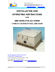
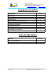

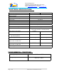
Table Of Contents

Dekolink WIRELESS Ltd.
16 Bazel St. Qiryat-Arieh Petah-Tikva, Israel, 49510
Tel- 972-3-9180-180 Fax-972-3- 190-9180
e-mail: marketing@decolink.com
web www.decolink.com
: ELECTRICAL SPECIFICATIONS
Frequency Range (MHz)
Uplink 1850-1910 MHz,
Downlink 1930-1990 MHz
Passband Gain @Min attenuation
80 dB nominal
Passband Ripple
± 1.8 dB typical
Manual Attenuation Range
0 to 30 dB in 2 dB step
Noise Figure
5.0 dB max
Impedance level
50 ohms
V.S.W.R In/Out
1.8 : 1 max
AGC Selection
By ON/OFF Switch
AGC Attenuation Range
25 dB typical
AGC LED Indication
LED turn ON when power reaches AGC Set
Power Level. (both at On and Off positions).
AGC Factory Power Preset
+24 dBm
Amplifier Power Output
@1 dB Compression
1 Watts
10Watts
3rd Order output Intercept point
45 dBm typical
50 dBm typical
Uplink 3rd Order IMD (dBc typ)
@ two tones +20 dBm each
50
Downlink 3rd Order IMD (dBc typ)
@ two tones +27 dBm each
45
Power Supply
110/220V AC, 50-60 Hz /1A
:ENVIRONMENTAL CONDITIONS
Operating temperature
- 30°
C to + 50
°
C
Storage temperature
- 50°
C to + 90
°
C
Page
7 of
8
CBDA-PCSAC-10W80 INST-FCC.doc